Briggs & Stratton Power Products Home Generator
Installation Manual
KNOW YOUR SYSTEM CONTROL BOARD
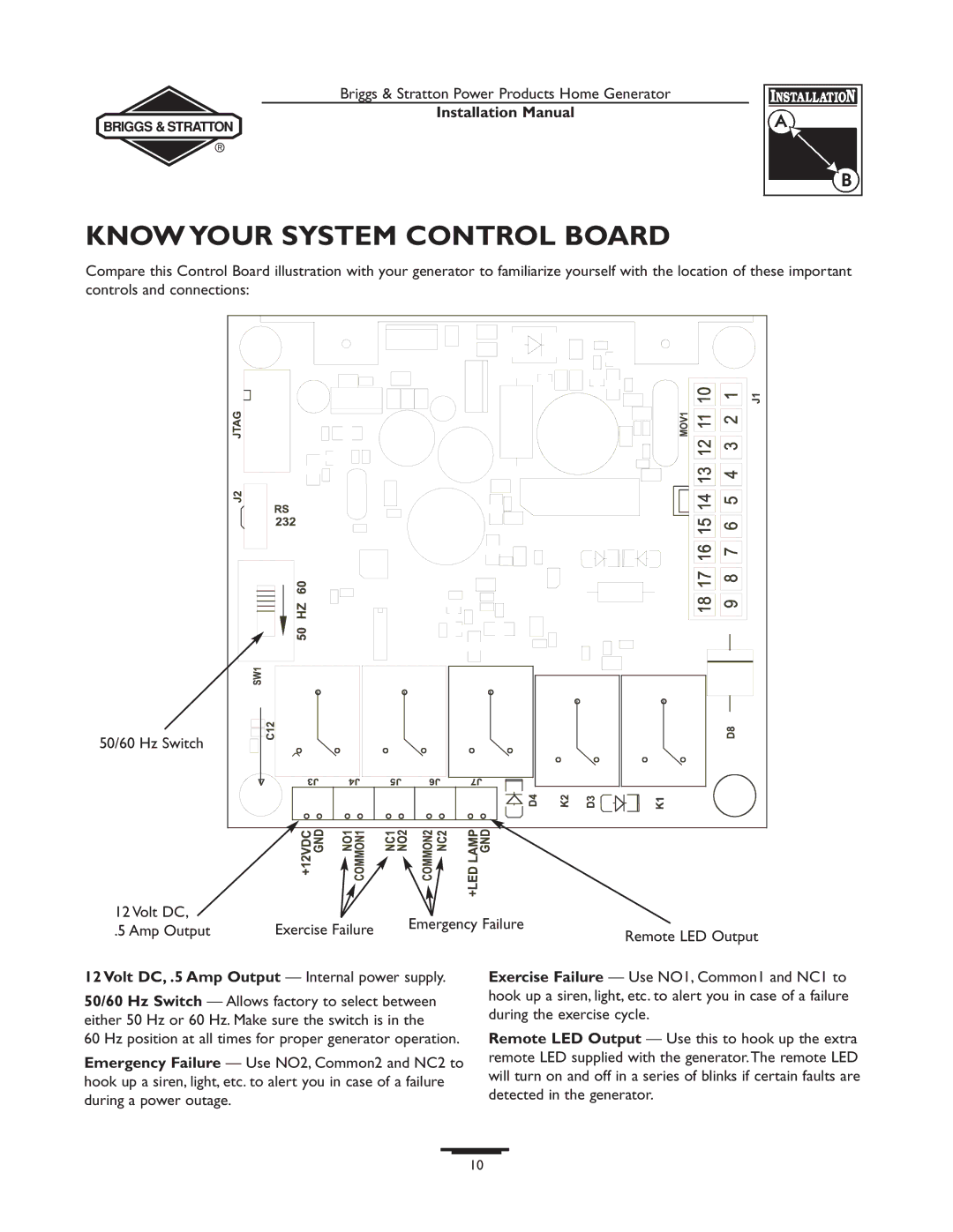
Compare this Control Board illustration with your generator to familiarize yourself with the location of these important controls and connections:
50/60 Hz Switch
12 Volt DC, | Exercise Failure | Emergency Failure | |
.5 Amp Output | |||
Remote LED Output | |||
|
|
12 Volt DC, .5 Amp Output — Internal power supply.
50/60 Hz Switch — Allows factory to select between either 50 Hz or 60 Hz. Make sure the switch is in the
60 Hz position at all times for proper generator operation.
Emergency Failure — Use NO2, Common2 and NC2 to hook up a siren, light, etc. to alert you in case of a failure during a power outage.
Exercise Failure — Use NO1, Common1 and NC1 to hook up a siren, light, etc. to alert you in case of a failure during the exercise cycle.
Remote LED Output — Use this to hook up the extra remote LED supplied with the generator.The remote LED will turn on and off in a series of blinks if certain faults are detected in the generator.
10