FEATURES AND CONTROLS
FEATURES AND CONTROLS
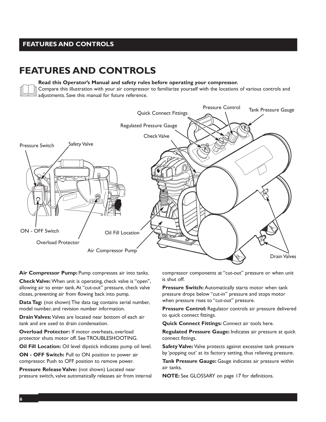
Read this Operator’s Manual and safety rules before operating your compressor.
Compare this illustration with your air compressor to familiarize yourself with the locations of various controls and adjustments. Save this manual for future reference.
Quick Connect Fittings | Pressure Control | Tank Pressure Gauge |
| ||
|
| |
Regulated Pressure Gauge |
|
|
Check Valve |
|
|
|
|
| Safety Valve | |
Pressure Switch | ||||
| ||||
|
|
|
| |
ON - OFF Switch | Oil Fill Location |
|
Overload Protector
Air Compressor Pump
Air Compressor Pump: Pump compresses air into tanks.
Check Valve: When unit is operating, check valve is “open”, allowing air to enter tank. At
Data Tag: (not shown) The data tag contains serial number, model number, and revision number information.
Drain Valves: Valves are located near bottom of each air tank and are used to drain condensation.
Overload Protector: If motor overheats, overload protector shuts motor off. See TROUBLESHOOTING.
Oil Fill Location: Oil level dipstick indicates pump oil level.
ON - OFF Switch: Pull to ON position to power air compressor. Push to OFF position to remove power.
Pressure Release Valve: (not shown) Located near pressure switch, valve automatically releases air from internal
Drain Valves
compressor components at
Pressure Switch: Automatically starts motor when tank pressure drops below
Pressure Control: Regulator controls air pressure delivered to quick connect fittings.
Quick Connect Fittings: Connect air tools here.
Regulated Pressure Gauge: Indicates air pressure at quick connect fittings.
Safety Valve: Valve protects against excessive tank pressure by ‘popping out’ at its factory setting, thus relieving pressure.
Tank Pressure Gauge: Gauge indicates air pressure within air tanks.
NOTE: See GLOSSARY on page 17 for definitions.
6