The manometer port permits temporary installation of a manometer to ensure that the engine receives the correct fuel pressure to operate efficiently throughout its operating range.
NOTE: A digital manometer, P/N 19495, is available at your local Briggs & Stratton service center.
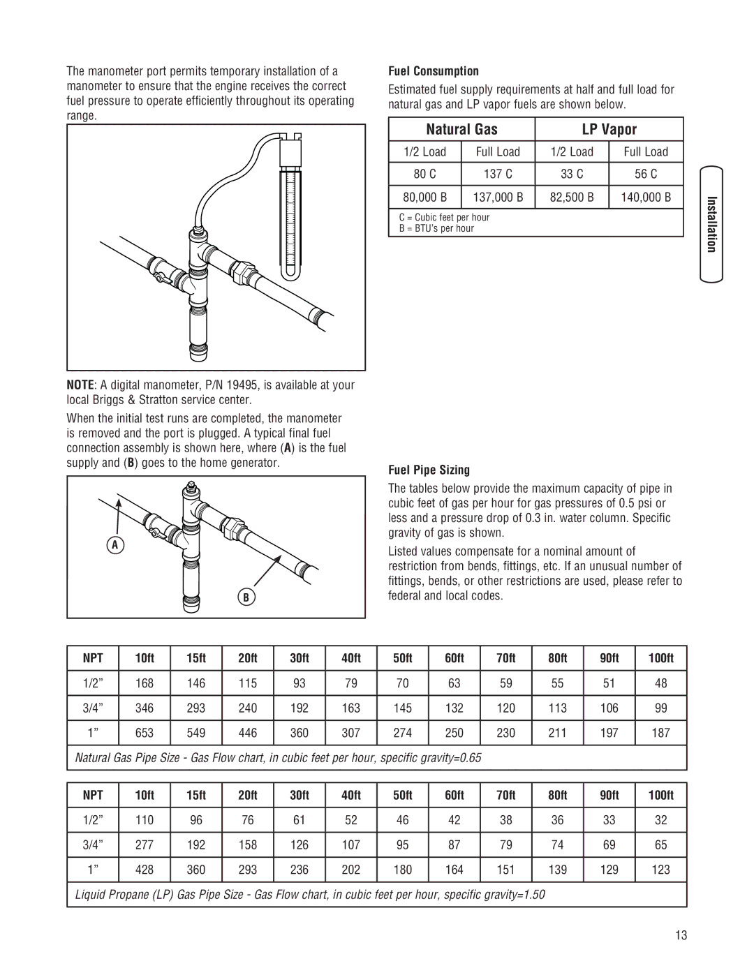
When the initial test runs are completed, the manometer is removed and the port is plugged. A typical final fuel connection assembly is shown here, where (A) is the fuel supply and (B) goes to the home generator.
A![]()
![]()
![]()
![]()
![]()
![]() B
B
Fuel Consumption
Estimated fuel supply requirements at half and full load for natural gas and LP vapor fuels are shown below.
Natural Gas | LP Vapor | ||
|
|
|
|
1/2 Load | Full Load | 1/2 Load | Full Load |
|
|
|
|
80 C | 137 C | 33 C | 56 C |
|
|
|
|
80,000 B | 137,000 B | 82,500 B | 140,000 B |
|
|
|
|
C = Cubic feet per hour
B = BTU’s per hour
Fuel Pipe Sizing
The tables below provide the maximum capacity of pipe in cubic feet of gas per hour for gas pressures of 0.5 psi or less and a pressure drop of 0.3 in. water column. Specific gravity of gas is shown.
Listed values compensate for a nominal amount of restriction from bends, fittings, etc. If an unusual number of fittings, bends, or other restrictions are used, please refer to federal and local codes.
NPT | 10ft | 15ft | 20ft | 30ft | 40ft | 50ft | 60ft | 70ft | 80ft | 90ft | 100ft |
|
|
|
|
|
|
|
|
|
|
|
|
1/2” | 168 | 146 | 115 | 93 | 79 | 70 | 63 | 59 | 55 | 51 | 48 |
|
|
|
|
|
|
|
|
|
|
|
|
3/4” | 346 | 293 | 240 | 192 | 163 | 145 | 132 | 120 | 113 | 106 | 99 |
|
|
|
|
|
|
|
|
|
|
|
|
1” | 653 | 549 | 446 | 360 | 307 | 274 | 250 | 230 | 211 | 197 | 187 |
|
|
|
|
|
|
|
|
|
|
|
|
Natural Gas Pipe Size - Gas Flow chart, in cubic feet per hour, specific gravity=0.65 |
|
|
|
| |||||||
|
|
|
|
|
|
|
|
|
|
|
|
NPT | 10ft | 15ft | 20ft | 30ft | 40ft | 50ft | 60ft | 70ft | 80ft | 90ft | 100ft |
|
|
|
|
|
|
|
|
|
|
|
|
1/2” | 110 | 96 | 76 | 61 | 52 | 46 | 42 | 38 | 36 | 33 | 32 |
|
|
|
|
|
|
|
|
|
|
|
|
3/4” | 277 | 192 | 158 | 126 | 107 | 95 | 87 | 79 | 74 | 69 | 65 |
|
|
|
|
|
|
|
|
|
|
|
|
1” | 428 | 360 | 293 | 236 | 202 | 180 | 164 | 151 | 139 | 129 | 123 |
|
|
|
|
|
|
|
|
|
|
|
|
Liquid Propane (LP) Gas Pipe Size - Gas Flow chart, in cubic feet per hour, specific gravity=1.50
13