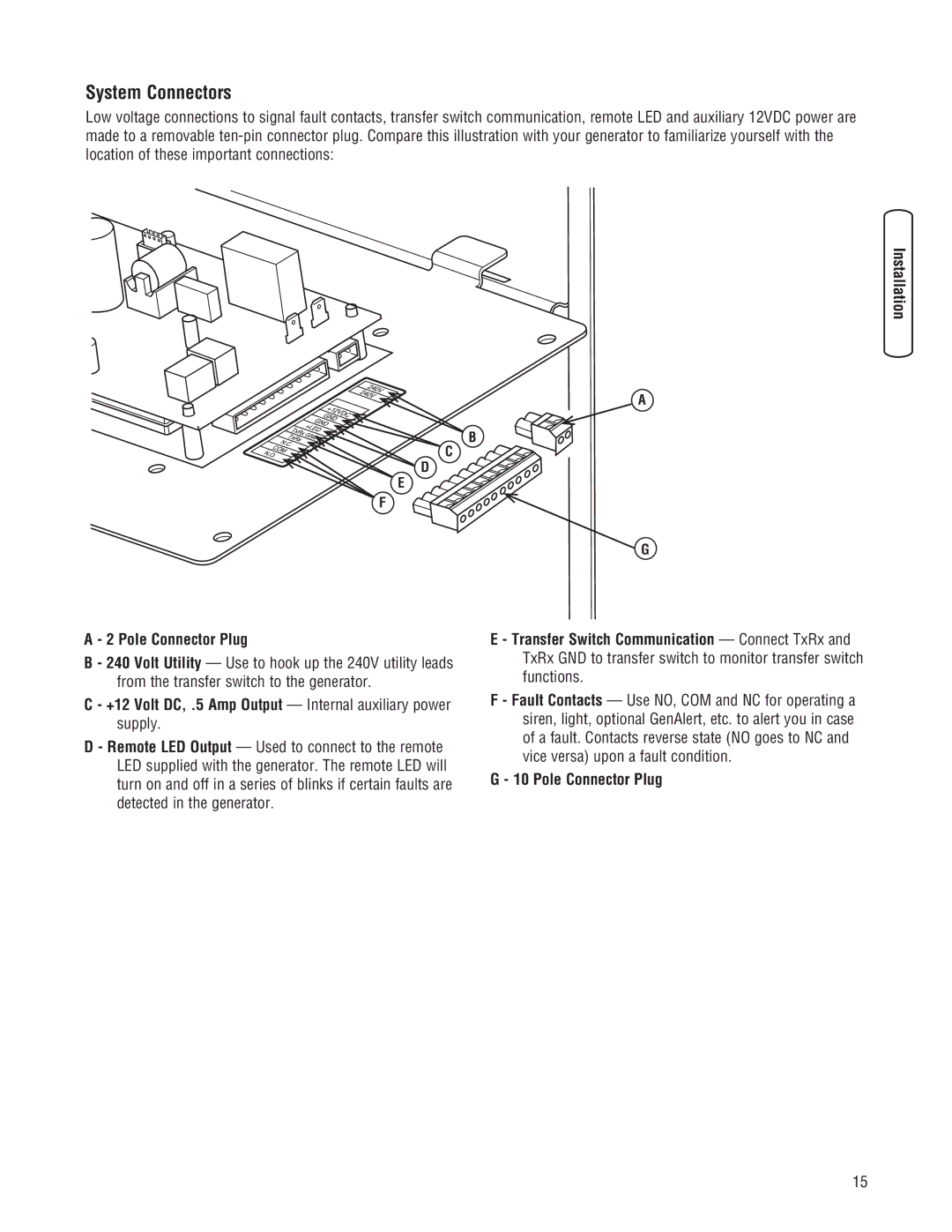
System Connectors
Low voltage connections to signal fault contacts, transfer switch communication, remote LED and auxiliary 12VDC power are made to a removable
A
B
C
D
E
F
G
A - 2 Pole Connector Plug
B - 240 Volt Utility — Use to hook up the 240V utility leads from the transfer switch to the generator.
C - +12 Volt DC, .5 Amp Output — Internal auxiliary power supply.
D - Remote LED Output — Used to connect to the remote LED supplied with the generator. The remote LED will turn on and off in a series of blinks if certain faults are detected in the generator.
E - Transfer Switch Communication — Connect TxRx and TxRx GND to transfer switch to monitor transfer switch functions.
F - Fault Contacts — Use NO, COM and NC for operating a siren, light, optional GenAlert, etc. to alert you in case of a fault. Contacts reverse state (NO goes to NC and vice versa) upon a fault condition.
G - 10 Pole Connector Plug
15