Battery
The installer must supply a sealed, rechargeable 12 Volt DC, 650 Cold Cranking Amps (CCA) 55 amp hour starting battery. The battery may not be at full charge when installed. If battery voltage is below 12 Volts, charge the battery. See Battery in Maintenance for details.
NOTE: DO NOT use a
Fuel Supply System
Ensure that all fuel pipe connections are tight, secure and without leaks.
Ensure that all gas line shutoff valves are OPEN and that adequate fuel pressure is available whenever automatic operation is desired.
Initial Start-up (No Load)
Before operating the home generator or placing it into service, inspect the entire installation carefully.
Then begin testing the system without any electrical loads connected, as follows:
NOTE: Unit has been
1.Set generator’s main circuit breaker to its ON (closed) position.
2.Confirm 15 Amp fuse is installed in control panel.
3.Set generator’s system switch to AUTO.
4.Push MANUAL
NOTE: When the generator is started for the very first time, it will require that air in the gaseous fuel lines be purged. This may take a few minutes.
5.DO NOT crank engine for more than 15 seconds, then pause for 15 seconds to reduce heat in the starter.
6.Repeat process until engine starts.
7.Listen for unusual noises, vibration or other indications of abnormal operation. Check for oil or coolant leaks while engine runs.
8.Let engine warm up for about five minutes to allow internal temperatures to stabilize.
9.Connect an accurate AC voltmeter and a frequency meter to check generator output at load side of circuit breaker.
NOTE: If AC voltage is outside these ranges, perform the generator adjustment, Steps 13 and 14 below.
10.Check generator output between one of the generator connection lugs and the neutral lug, then between the other generator connection lug and the neutral lug.
In both cases, voltage reading should be between 117‑123 Volts.
11.Push and hold MANUAL
IMPORTANT: DO NOT proceed until you are certain that generator AC voltage is correct and within the stated limits. Generator frequency is fixed and not adjustable
12.If voltage and frequency values are correct, proceed to step 15.
13.Connect voltmeter as described in step 9 above.
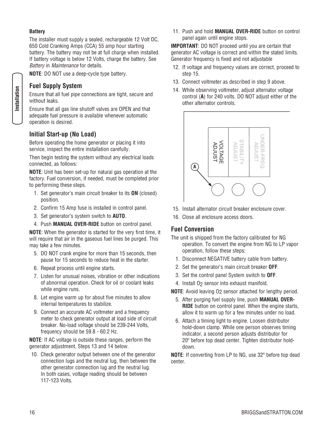
14.While observing voltmeter, adjust alternator voltage control (A) for 240 volts. DO NOT adjust either of the other alternator controls.
A | ADJUST | VOLTAGE | STABILITY ADJUST | |
|
|
| . | |
|
|
|
|
|
15.Install alternator circuit breaker enclosure cover.
16.Close all enclosure access doors.
Fuel Conversion
The unit is shipped from the factory calibrated for NG operation. To convert the engine from NG to LP vapor operation, follow these steps:
1.Disconnect NEGATIVE battery cable from battery.
2.Set the generator’s main circuit breaker OFF.
3.Set the control panel System switch to OFF.
4.Install O2 sensor into exhaust manifold.
NOTE: Avoid leaving O2 sensor attached for lengthy period.
5.After purging fuel supply line, push MANUAL OVER- RIDE button on control panel. When the engine starts, allow it to warm up for a few minutes under no load.
6.Attach a timing light to engine. Loosen distributor
NOTE: If converting from LP to NG, use 32º before top dead center.
16 | BRIGGSandSTRATTON.COM |
