Installation
Unpacking
Delivery Inspection
After removing the carton, carefully inspect the transfer switch components for any damage that may have occurred during shipment.
IMPORTANT: If loss or damage is noted at time of delivery, have the person(s) making delivery note all damage on the freight bill and affix his signature under the consignor's memo of loss or damage. If loss or damage is noted after delivery, contact the carrier for claim procedures. Missing or damaged parts are not warranted.
Shipment Contents
•Automatic Power Transfer Switch
•Two Current Transformers
•Installation and Operator’s Manual
Mounting Guidelines
The Automatic Transfer Switch is enclosed in NEMA Type 3R enclosures suitable for indoor or indoor/outdoor use.
Guidelines for mounting the Automatic Transfer Switch include:
•Install the switch on a firm, sturdy supporting structure.
•The switch must be installed with minimum NEMA 3R hardware for conduit connections.
•To prevent switch contact distortion, level and plumb the enclosure. This can be done by placing washers between the switch enclosure and the mounting surface.
•Never install the switch where any corrosive substance might drip onto the enclosure.
•Protect the switch at all times against excessive moisture, dust, dirt, lint, construction grit and corrosive vapors.
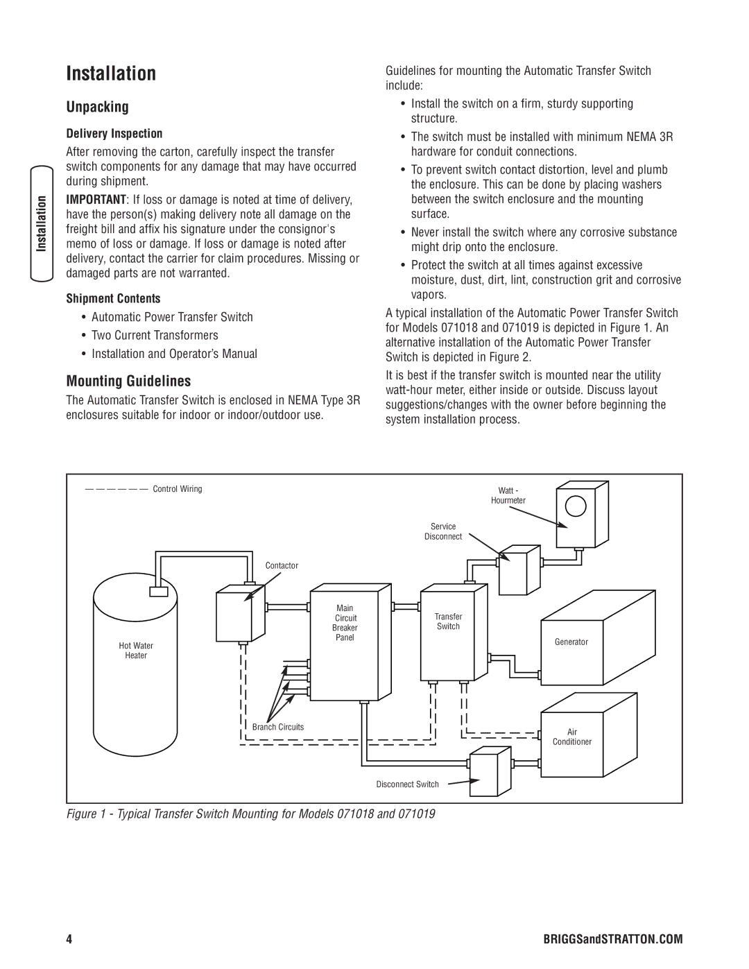
A typical installation of the Automatic Power Transfer Switch for Models 071018 and 071019 is depicted in Figure 1. An alternative installation of the Automatic Power Transfer Switch is depicted in Figure 2.
It is best if the transfer switch is mounted near the utility
— — — — — — Control Wiring | Watt - | |
| Hourmeter | |
| Service | |
| Disconnect | |
Contactor |
| |
Main | Transfer | |
Circuit | ||
Breaker | Switch | |
Panel | Generator | |
Hot Water | ||
| ||
Heater |
| |
Branch Circuits | Air | |
| ||
| Conditioner | |
| Disconnect Switch |
Figure 1 - Typical Transfer Switch Mounting for Models 071018 and 071019
4 | BRIGGSandSTRATTON.COM |