8.Connect Neutral conductor from the generator control panel to the transfer switch “NEUTRAL” terminal.
9.Connect generator Ground conductor from the control panel to the transfer switch “GND” terminal.
NOTE: Assure generator equipment grounding conductor is connected per applicable federal, state and local codes, standards and regulations.
10.Connect generator “UTILITY 240 VAC” terminals to transfer switch “UTILITY 240 VAC” terminals. Use minimum #14 AWG conductors.
11.Tighten all wire connections/fasteners to proper torque. See inside transfer switch enclosure for proper torque values.
Supervisory Control Wiring
1.Terminal strip on control module in transfer switch has four connections for customer use. There are two sets of “Normally Closed” contacts available. They will be activated when generator power is required. These can be used for supervisory control of large connected loads on generator. Loads will be allowed to operate if there is enough generator power available.
NOTE: There are two wireways provided to keep the supervisory loads separated from each other.
2.Terminals
Air Conditioner Contactor
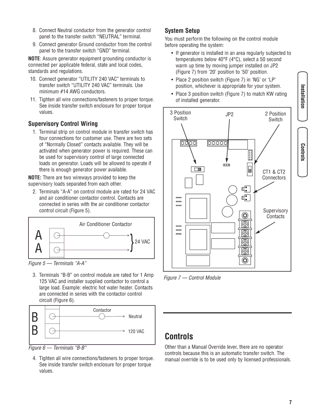
System Setup
You must perform the following on the control module before operating the system:
•If generator is installed in an area regularly subjected to temperatures below 40°F (4°C), select a 50 second warm up time by moving jumper installed on JP2 (Figure 7) from ‘20’ position to ‘50’ position.
•Place 2 position switch (Figure 7) in ‘NG’ or ‘LP’ position, whichever is appropriate for your system.
•Place 3 position switch (Figure 7) to match KW rating of installed generator.
3 Position | JP2 | 2 Position |
Switch |
| Switch |
|
| CT1 & CT2 |
|
| Connectors |
|
| Supervisory |
|
| Contacts |
A A
24 VAC
Figure 5 — Terminals “A-A”
3.Terminals
B | Contactor | |
Neutral | ||
B | ||
120 VAC | ||
|
Figure 6 — Terminals “B-B”
4.Tighten all wire connections/fasteners to proper torque. See inside transfer switch enclosure for proper torque values.
Figure 7 — Control Module
Controls
Other than a Manual Override lever, there are no operator controls because this is an automatic transfer switch. The manual override is to be used only by licensed professionals.
7