Manual No GS Revision a 02/25/2009
Operator’s Manual
Date Purchased
Where to Find Us
Generator
Engine
Table of Contents
Equipment Description
Operator Safety
Important Safety Information
Safety Symbols and Meanings
Fire or explosion can cause severe burns or death
Monoxide, an odorless, colorless, poison gas
Nausea, fainting or death
Hydrogen gas during recharging
Excessively low speeds impose a heavy load
Fuel tank causing a fire
When Testing for Engine Spark
Unpack Generator
Assembly
Install Wheel Kit
Shipment Contents
Tip generator so that engine end is up
Attach Negative Battery Cable
To install
High Altitude
Add Engine Oil
Add Fuel
Fuel must meet these requirements
Special Requirements
Connecting to a Building’s Electrical System
System Ground
Generator Location
Recoil Starter Used to start the engine manually
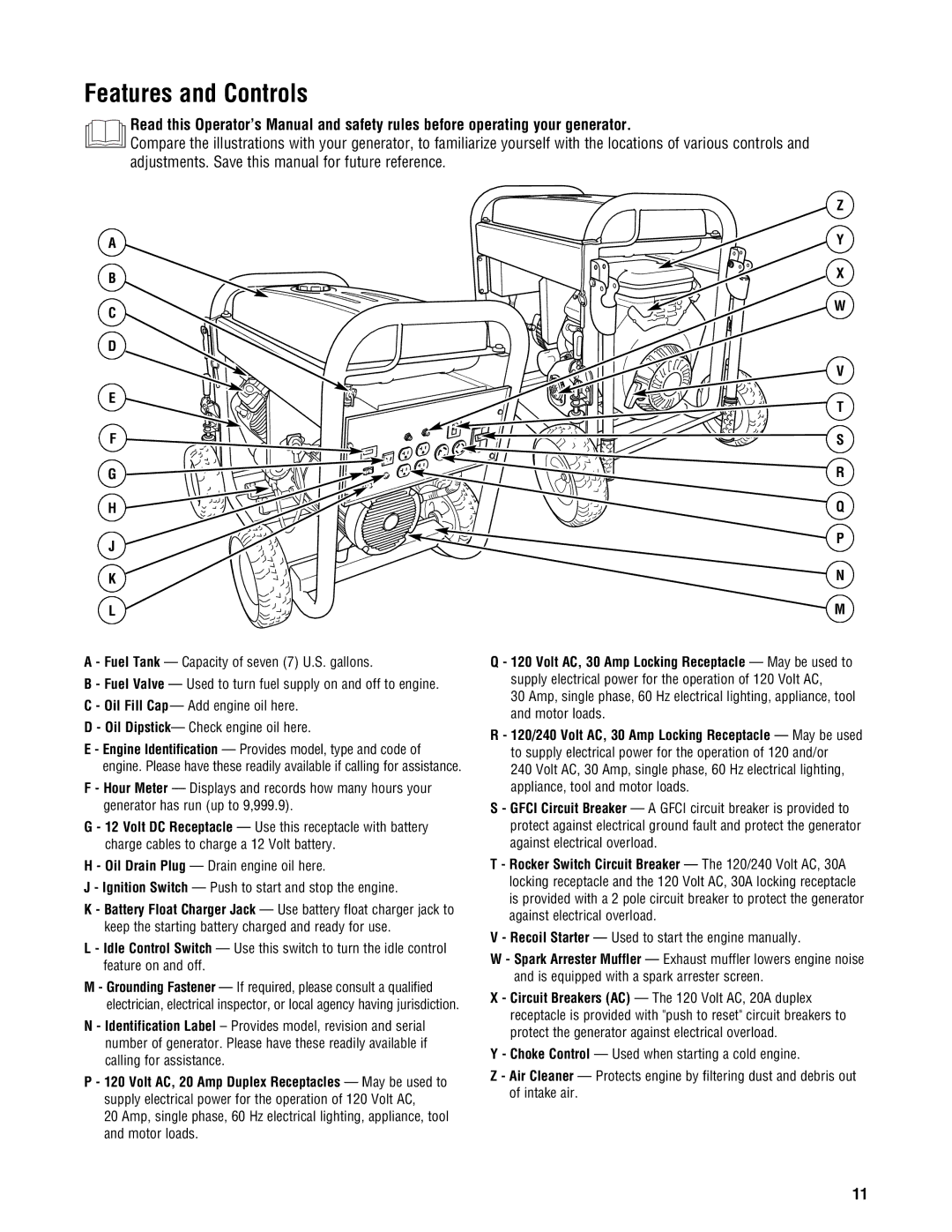
Features and Controls
Nema L5-30
Cord Sets and Receptacles
Nema L14-30
Test your Gfci circuit breaker every month, as follows
Ground Fault Protection
Battery Charger
Test Gfci Circuit Breaker
Starting the Engine
Connecting Electrical Loads
Operation
Oil Pressure Shutdown
Charging a Battery
Stopping the Engine
Operating Automatic Idle Control
Building a Cold Weather Shelter
Cold Weather Operation
Creating a Temporary Cold Weather Shelter
Wattage Reference Guide
Don’t Overload Generator
Battery Maintenance
Maintenance
Maintenance Schedule
Generator Maintenance
Checking Oil Level
Fuel Valve Maintenance
Engine Maintenance
Oil Recommendations
Changing Engine Oil and Filter
Service Air Cleaner
To service the air cleaner, follow these steps
Service Spark Plugs
Inspect Muffler and Spark Arrester
Clean and inspect the spark arrester as follows
Clean Cooling System
Carburetor Adjustment
Change Engine Oil
Storage
Generator Storage
Long Term Storage Instructions
Troubleshooting
BRIGGSandSTRATTON.COM
Page
Briggs & Stratton Emissions Control Warranty Provisions
Your Warranty Rights And Obligations
Manufacturer’s Warranty Coverage
Owner’s Warranty Responsibilities
Extended
Warranty on emissions-related parts is as follows
Moderate
Intermediate
Limited Warranty
Reserved
800
Product Specifications
Common Service Parts
Manual del Operario
Fecha de compra
Dónde encontrarnos
Generador
Motor
Controles y características
Resolución de problemas Garantías
Seguridad de operario
Montaje
Símbolos sobre la seguridad y significados
Seguridad de operario
Descripción del equipo
Información importante de seguridad
Cuando Opere EL Equipo
Cuando Anada Combustible O Vacíe EL Depósito
Cuando Ponga EN Funcionamiento EL Equipo
No arranque el motor sin la bujía instalada
No modifique al generador en ninguna forma
Cuando Ajuste O Haga Reparaciones a SU Máquina Generador
Cuando Pruebe LA Bujía DEL Motor
Instale el juego de ruedas
Montaje
Desembalaje del generador
Contenido de la caja
Para instalar
Conecte el cable negativo de la batería
Suba el asas e inserte su pasador para mover el generador
Gran altitud
Agregar aceite al motor
Agregue combustible
El combustible debe reunir los siguientes requisitos
Requisitos especiales
Tierra del sistema
Conexión al sistema eléctrico de un edificio
Ubicación del generador
Culatazo el Principio Usó para comenzar motor manualmente
Controles y características
Amperios, monofásica de 60 Hz
Tomacorriente con Dispositivo de Seguridad de
Neutro Cargado Tierra Verde
Juegos de cordones y enchufes conectores
Juego de Cable de 3 Alambres
Cargador de batería
Protección contra fallos de conexión a tierra
Si el motor no arranca, repita los pasos desde 4 hasta
Operando
Encienda el motor
Parada por falta de presión de aceite
Conexión de cargas eléctricas
Parada del motor
Funcionamiento del control automático de marcha en vacío
Limpie los terminales de la batería si es necesario
Carga de la bateria
Operación durante un clima frío
Page
Control de la energía
No sobrecargar el generador
Capacidad
Ejemplo
Mantenimiento de la batería
Mantenimiento
Plan de mantenimiento
Mantenimiento del generador
Mantenimiento del motor
Mantenimiento de la válvula de combustible
Quite la varilla de nivel de aceite
Instale el varilla de medición, apriete firmemente
Cambio de aceite del motor y filtro
Coloque el tapón de vaciado y apriételo bien
Sistema de refrigeración de aire
Servicio del bujía
Inspeccione el silenciador y la pantalla apagachispas
Limpie e inspeccione el apagachispas de la siguiente manera
Cambio de Aceite
Almacenamiento
Generador
Almacenamiento para periodos prolongados
Problemo Causa Accion
Resolución de problemas
Conectores y unidades Duración de la cobertura
Garantías
Cobertura de la garantía del fabricante
Responsabilidades de la garantía del propietario
BRIGGSandSTRATTON.COM
Garantía Limitada
Servicio común despide
Especificaciones del producto
Manuel d’utilisation
Date d’achat
Où nous trouver
Génératrice
Moteur
Opération
Fonctions et commandes
Sécurité de l’opérateur
Assemblage
Renseignements importants de sécurité
Symboles de sécurité et leur signification
Sécurité de l’opérateur
Description de l équipement
Lorsque Léquipement Fonctionne
Explosives
Lors DE Lajout OU DE LA Vidange DU Carburant
Lors DU Démarrage DE Léquipement
Lors DE Tests Dallumage DU Moteur
Avertissement Le génératrice produit une tension élevée
NE Touchez PAS les fils dénudés ou les boîtiers
Lorsque Vous Réglez OU Réparez Votre Génératrice
Contenu de l’expédition
Installe la roue la trousse
Assemblage
Déballez la génératrice
Rattachez la vis au terminal négative de pile et serrez
Installation
Raccordez le câble de retour de la batterie
Replacez la génératrice à sa positon normale sur les roues
Avis Évitez d’endommager le génératrice
Ajoutez de lhuile à moteur
Ajoutez de lessence
’essence satisfait les exigences suivantes
Dégagement de la génératrice
Emplacement de la génératrice
Mise à la terre du système
Exigences spéciales
Chargeur à tampon de batterie Utilisez la prise du chargeur
Fonctions et commandes
Et/ou des dommages matériels
Cordons et prises
Pendant le fonctionnement de la génératrice
Protection contre les fuites de terre
Chargeur de batterie
Mise à lessai du disjoncteur Gfci
Démarrage du moteur
Opération
Arrêt du moteur en cas de bas niveau d’huile
Branchement des charges électriques
Arrêt du moteur
Fonctionnement du contrôle automatique du ralenti
Protégez lunité contre les intempéries
Recharge d’une batterie
Fonctionnement par temps froid
Si nécessaire, nettoyer les bornes de la batterie
Vent
Création d’un abri temporaire pour les temps froids
Création d’un abri pour les temps froids
Gestion de la consommation
Ne pas surchargez générateur
Exemple
Entretien de génératrice
Entretien
Calendrier dentretien
Entretien du moteur
Huile Recommandations relatives à l’huile
Entretien de la batterie
Entretien de la vanne de combustible
Secondes pour laisser couler lhuile
Vérification du niveau dhuile
Ajout d’huile
Changement d’huile à moteur et de filtre
Inspectez le silencieux et l’écran pare-étincelles
Entretien du filtre à air
Décrochez les verrous a des deux côtés du
Entretien de la bougies dallumage
Vérifier le jeu des soupapes
Nettoyez et inspectez le pare-étincelles comme suit
Remettez l’écran en place et fixez-le avec quatre vis
Nettoyer le système de refroidissement
Autres idées de remisage
Entreposage
Entreposage de la génératrice
Changement de lhuile
Dépannage
Pièces garanties
Garanties
Vos droits et obligations relatifs à la garantie
Couverture de garantie du fabricant
Catégorie B = 250 heures Catégorie a = 500 heures
Garantie Limitée
Réservé
Pièces d’entretien courant
Caractéristiques du produit