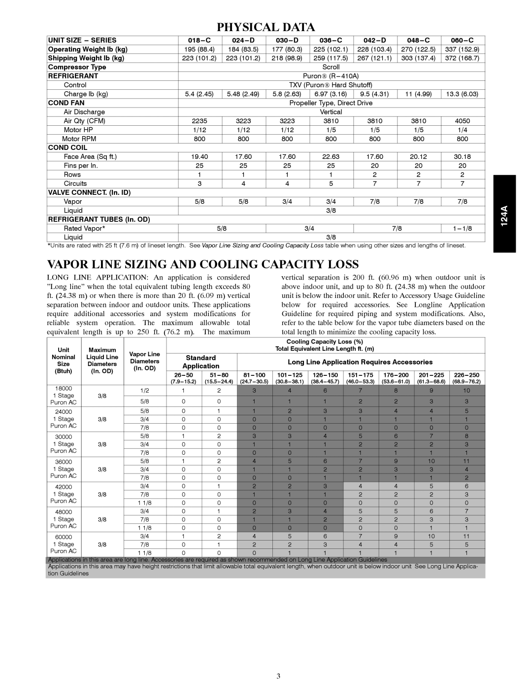
PHYSICAL DATA

UNIT SIZE --- SERIES

018---C

024---D

030---D

036---C

042---D

048---C

060---C

Operating Weight lb (kg)

195 (88.4)

184 (83.5)

177 (80.3)

225 (102.1)

228 (103.4)

270 (122.5)

337 (152.9)

Shipping Weight lb (kg)

223 (101.2)

223 (101.2)

218 (98.9)

259 (117.5)

267 (121.1)

303 (137.4)

372 (168.7)

Compressor Type


Scroll


REFRIGERANT


Puron(R--- 410A)


Control


TXV (PuronHard Shutoff)


Charge lb (kg)

5.4 (2.45)

5.48 (2.49)

5.8 (2.63)

6.97 (3.16)

9.5 (4.31)

11 (4.99)

13.3 (6.03)

COND FAN


Propeller Type, Direct Drive


Air Discharge


Vertical


Air Qty (CFM)

2235

3223

3223

3810

3810

3810

4050

Motor HP

1/12

1/12

1/12

1/5

1/5

1/5

1/4

Motor RPM

800

800

800

800

800

800

800

COND COIL


Face Area (Sq ft.)

19.40

17.60

17.60

22.63

17.60

20.12

30.18

Fins per In.

25

25

25

25

20

20

20

Rows

1

1

1

1

2

2

2

Circuits

3

4

4

5

7

7

7

VALVE CONNECT. (In. ID)


Vapor

5/8

5/8

3/4

3/4

7/8

7/8

7/8

Liquid


3/8


REFRIGERANT TUBES (In. OD)


Rated Vapor*


5/8


3/4


7/8

1--- 1/8

Liquid


3/8


*Units are rated with 25 ft (7.6 m) of lineset length. See Vapor Line Sizing and Cooling Capacity Loss table when using other sizes and lengths of lineset.

VAPOR LINE SIZING AND COOLING CAPACITY LOSS


LONG LINE APPLICATION: An application is considered

vertical separation is 200 ft. (60.96 m) when outdoor unit is


”Long line” when the total equivalent tubing length exceeds 80

above indoor unit, and up to 80 ft. (24.38 m) when the outdoor


ft. (24.38 m) or when there is more than 20 ft. (6.09 m) vertical

unit is below the indoor unit. Refer to Accessory Usage Guideline


separation between indoor and outdoor units. These applications

below for required accessories. See Longline Application


require additional accessories and system modifications for

Guideline for required piping and system modifications. Also,


reliable system operation. The maximum allowable total

refer to the table below for the vapor tube diameters based on the


equivalent

length is up

to 250 ft.

(76.2 m).

The maximum

total length to minimize the cooling capacity loss.


Cooling Capacity Loss (%)


Unit

Maximum

Vapor Line


Total Equivalent Line Length ft. (m)


Nominal

Liquid Line


Standard


Diameters


Long Line Application Requires Accessories


Size

Diameters


Application


(Btuh)

(In. OD)

(In. OD)


26---50

51---80

81---100

101---125

126---150

151---175

176---200

201---225

226---250


(7.9---15.2)

(15.5---24.4)

(24.7---30.5)

(30.8---38.1)

(38.4---45.7)

(46.0---53.3)

(53.6---61.0)

(61.3---68.6)

(68.9---76.2)


18000


1/2


1

2

3

4

6

7

8

9

10


1 Stage

3/8


5/8


0

0

1

1

1

2

2

3

3


Puron AC


24000


5/8


0

1

1

2

3

3

4

4

5


1 Stage

3/8

3/4


0

0

0

0

1

1

1

1

1


Puron AC


7/8


0

0

0

0

0

0

0

0

0


30000


5/8


1

2

3

3

4

5

6

7

8


1 Stage

3/8

3/4


0

0

1

1

1

2

2

2

3


Puron AC


7/8


0

0

0

0

1

1

1

1

1


36000


5/8


1

2

4

5

6

7

9

10

11


1 Stage

3/8

3/4


0

0

1

1

2

2

3

3

4


Puron AC


7/8


0

0

0

0

1

1

1

1

2


42000


3/4


0

1

2

2

3

4

4

5

6


1 Stage

3/8

7/8


0

0

1

1

1

2

2

2

3


Puron AC


1 1/8


0

0

0

0

0

0

0

0

0


48000


3/4


0

1

2

3

4

5

5

6

7


1 Stage

3/8

7/8


0

0

1

1

2

2

2

3

3


Puron AC


1 1/8


0

0

0

0

0

0

0

1

1


60000


3/4


1

2

4

5

6

7

9

10

11


1 Stage

3/8

7/8


0

1

2

2

3

4

4

5

5


Puron AC


1 1/8


0

0

0

1

1

1

1

1

1


Applications

in this area are

long line. Accessories are required as shown recommended on Long Line Application Guidelines


Applications in this area may have height restrictions that limit allowable total equivalent length, when outdoor unit is below indoor unit

See Long Line Applica-


tion Guidelines


124A

3

Page 3
Image 3
Bryant 124A manual Physical Data, Vapor Line Sizing and Cooling Capacity Loss

124A specifications

The Bryant 124A is a highly regarded heating and cooling unit, well-known for its efficient performance and reliability in residential settings. This air conditioning and heating system is designed to provide optimal comfort throughout the year while integrating seamlessly into a variety of home environments.

One of the main features of the Bryant 124A is its efficiency rating. The system boasts a Seasonal Energy Efficiency Ratio (SEER) rating of up to 16, making it an energy-conscious choice for homeowners. This high efficiency not only helps reduce energy costs but also contributes to a smaller carbon footprint, aligning with environmentally friendly practices.

The Bryant 124A utilizes advanced ComfortHeat technology, which ensures even temperature distribution throughout the home. This feature minimizes hot and cold spots, allowing for a comfortable living space regardless of external weather conditions. The system is equipped with a variable speed compressor, which adjusts its operation based on the immediate cooling or heating demands, further enhancing its energy efficiency and reducing wear and tear on the system.

In terms of reliability, the Bryant 124A is built with high-quality materials designed to withstand the rigors of changing weather conditions. It comes with a robust cabinet that provides protection against corrosion, ensuring longevity and reducing maintenance needs over time. Additionally, it features a lightweight design for easier installation, making it suitable for both new constructions and retrofits.

An added advantage of the Bryant 124A is its compatibility with smart thermostats, enabling homeowners to control their heating and cooling systems remotely through mobile apps. This integration allows for customizable settings based on individual preferences and schedules, further enhancing energy savings.

The Bryant 124A is also designed with noise reduction technology, ensuring quieter operation compared to conventional systems. This makes it an ideal choice for homes where noise levels are a concern.

In summary, the Bryant 124A is a versatile and efficient heating and cooling system packed with advanced technologies and features designed to provide comfort and reliability. With its energy efficiency, durability, and smart integration, it stands out as a favored option for homeowners seeking a dependable climate control solution.