NOTE: Pressure test the gas supply system after the gas supply piping is connected to the gas valve. The supply piping must be disconnected from the gas valve during the testing of the piping systems when test pressure is in excess of 0.5 psig (3450 Pa). Pressure test the gas supply piping system at pressures equal to or less than 0.5 psig (3450 Pa). The unit heating section must be isolated from the gas piping system by closing the external main manual shutoff valve and slightly opening the ground-joint union.

Check for gas leaks at the field-installed and factory-installed gas lines after all piping connections have been completed. Use soap-and-water solution (or method specified by local codes and/or regulations).


!

WARNING


581J

FIRE OR EXPLOSION HAZARD

Failure to follow this warning could result in personal


injury, death and/or property damage.

SConnect gas pipe to unit using a backup wrench to

avoid damaging gas controls.

SNever purge a gas line into a combustion chamber. S Never test for gas leaks with an open flame. Use a

commercially available soap solution made specifically for the detection of leaks to check all connections.

S Use proper length of pipe to avoid stress on gas control manifold.

NOTE: If orifice hole appears damaged or it is suspected to have been redrilled, check orifice hole with a numbered drill bit of correct size. Never redrill an orifice. A burr-free and squarely aligned orifice hole is essential for proper flame characteristics.

Step 11 — Install External Condensate Trap and Line

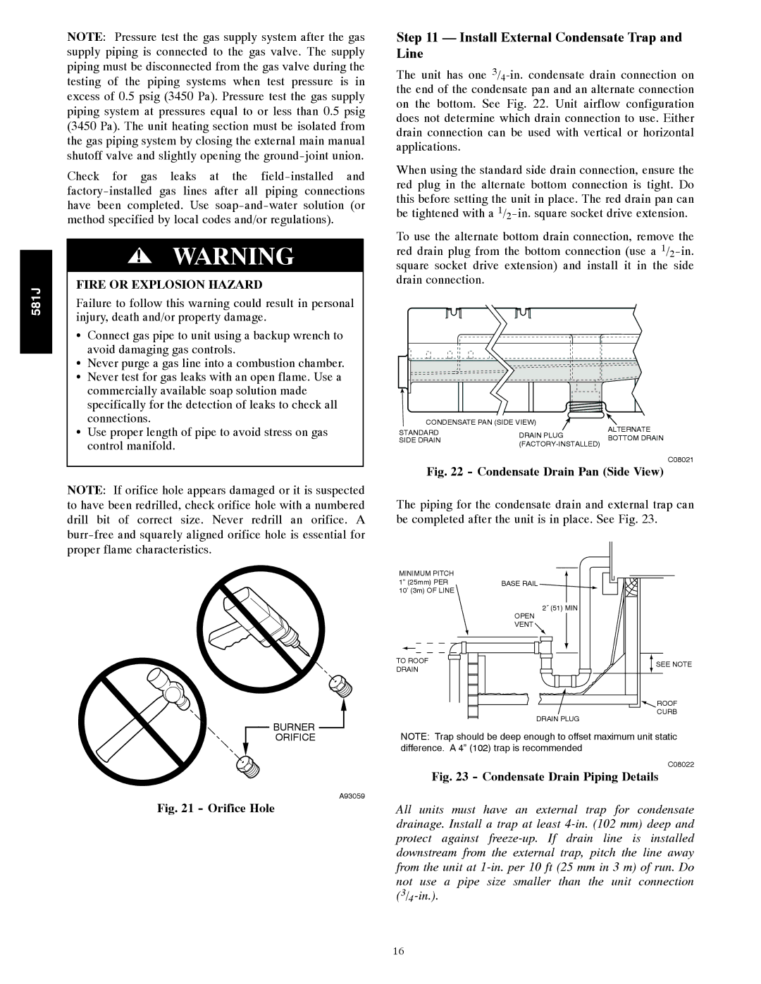
The unit has one 3/4-in. condensate drain connection on the end of the condensate pan and an alternate connection on the bottom. See Fig. 22. Unit airflow configuration does not determine which drain connection to use. Either drain connection can be used with vertical or horizontal applications.

When using the standard side drain connection, ensure the red plug in the alternate bottom connection is tight. Do this before setting the unit in place. The red drain pan can be tightened with a 1/2-in. square socket drive extension.

To use the alternate bottom drain connection, remove the red drain plug from the bottom connection (use a 1/2-in. square socket drive extension) and install it in the side drain connection.

CONDENSATE PAN (SIDE VIEW)


ALTERNATE

STANDARD

DRAIN PLUG

BOTTOM DRAIN

SIDE DRAIN

(FACTORY-INSTALLED)


C08021

Fig. 22 - Condensate Drain Pan (Side View)

The piping for the condensate drain and external trap can be completed after the unit is in place. See Fig. 23.

BURNER

MINIMUM PITCH

1” (25mm) PER

10’ (3m) OF LINE

TO ROOF

DRAIN

BASE RAIL

2˝ (51) MIN

OPEN

VENT

SEE NOTE

ROOF

CURB

DRAIN PLUG

ORIFICE

A93059

Fig. 21 - Orifice Hole

NOTE: Trap should be deep enough to offset maximum unit static difference. A 4” (102) trap is recommended.

C08022

Fig. 23 - Condensate Drain Piping Details

All units must have an external trap for condensate drainage. Install a trap at least 4-in. (102 mm) deep and protect against freeze-up. If drain line is installed downstream from the external trap, pitch the line away from the unit at 1-in. per 10 ft (25 mm in 3 m) of run. Do not use a pipe size smaller than the unit connection (3/4-in.).

16

Page 16
Image 16
Bryant 581J installation instructions Install External Condensate Trap and Line, Condensate Drain Pan Side View

581J specifications

The Bryant 581J is a high-efficiency gas furnace that exemplifies advanced heating technology and innovative design. Known for its reliability and comfort, the Bryant 581J offers impressive performance features that cater to both residential and commercial heating needs. One of its standout characteristics is the two-stage heating system, which allows the furnace to operate at a lower stage when the heating demand is modest, providing improved comfort and energy efficiency. This feature also minimizes temperature fluctuations, ensuring a more consistent and comfortable indoor environment.

Energy efficiency is a critical aspect of the Bryant 581J. With an annual fuel utilization efficiency (AFUE) rating of up to 96%, this furnace is designed to convert a high percentage of fuel into usable heat, which helps homeowners save on energy bills. The high-efficiency design also contributes to a reduced carbon footprint, aligning with modern environmental concerns.

The Bryant 581J is equipped with technologically advanced features, including the ComfortTechâ„¢ control system. This system enables enhanced temperature regulation and integrates easily with smart home systems, allowing homeowners the convenience of remote control through smartphones and tablets. Additionally, the furnace includes an electronically commutated motor (ECM) blower, which optimizes airflow and reduces energy consumption while enhancing the overall comfort level within the space.

Noise reduction is another key characteristic of the Bryant 581J. The furnace is engineered with sound-dampening technology, resulting in quieter operation compared to conventional furnaces. This attention to noise management makes it an appealing choice for residential applications, where peace and tranquility are crucial.

The durable construction of the Bryant 581J ensures longevity and reliability. With a robust cabinet and quality materials, it is built to withstand the rigors of daily operation. Furthermore, the furnace comes with a warranty that provides peace of mind, protecting the investment over the years.

Overall, the Bryant 581J represents a blend of efficiency, advanced technology, and reliable performance. With its high AFUE rating, innovative features, and quiet operation, it stands out in the market as a top choice for anyone seeking a dependable heating solution. Whether for new installations or replacements, the Bryant 581J is designed to meet the heating demands of today's energy-conscious homeowners.