takes the appropriate action to shut down fans and blowers, change over air handling systems, notify the fire alarm control panel, etc.

The sensor uses a process called differential sensing to prevent gradual environmental changes from triggering false alarms. A rapid change in environmental conditions, such as smoke from a fire, causes the sensor to signal an alarm state but dust and debris accumulated over time does not.

For installations using two sensors, the duct smoke detector does not differentiate which sensor signals an alarm or trouble condition.

Duct smoke sensor

Smoke Detector Sensor

C08245

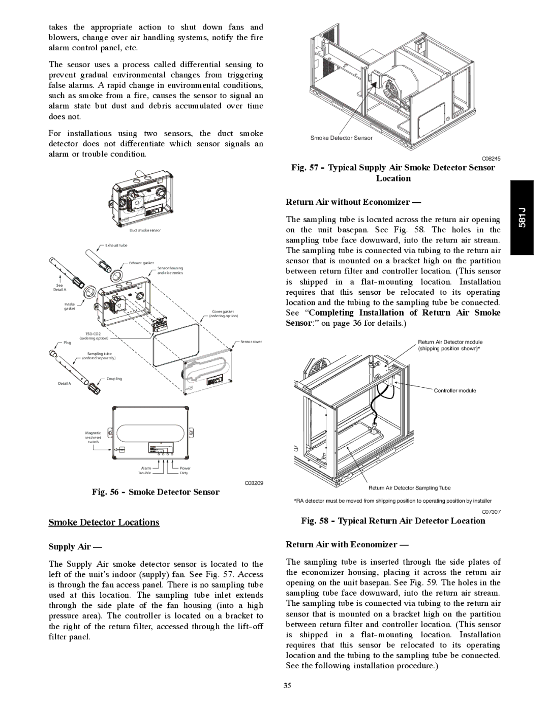
Fig. 57 - Typical Supply Air Smoke Detector Sensor

Location

Return Air without Economizer —

The sampling tube is located across the return air opening on the unit basepan. See Fig. 58. The holes in the sampling tube face downward, into the return air stream.

581J

Exhaust tube

Exhaust gasket

See

Detail A

Intake gasket

TSD-CO2 (ordering option)

Plug

Sampling tube

(ordered separately)

Coupling

Detail A

Magnetic test/reset switch

Sensor housing and electronics

Cover gasket

(ordering option)

Sensor cover

The sampling tube is connected via tubing to the return air sensor that is mounted on a bracket high on the partition between return filter and controller location. (This sensor is shipped in a flat-mounting location. Installation requires that this sensor be relocated to its operating location and the tubing to the sampling tube be connected.

See “Completing Installation of Return Air Smoke

Sensor:” on page 36 for details.)

Return Air Detector module (shipping position shown)*

Controller module

Alarm

Power

Trouble

Dirty

C08209

Fig. 56 - Smoke Detector Sensor

Smoke Detector Locations

Supply Air —

The Supply Air smoke detector sensor is located to the left of the unit’s indoor (supply) fan. See Fig. 57. Access is through the fan access panel. There is no sampling tube used at this location. The sampling tube inlet extends through the side plate of the fan housing (into a high pressure area). The controller is located on a bracket to the right of the return filter, accessed through the lift-off filter panel.

Return Air Detector Sampling Tube

*RA detector must be moved from shipping position to operating position by installer

C07307

Fig. 58 - Typical Return Air Detector Location

Return Air with Economizer —

The sampling tube is inserted through the side plates of the economizer housing, placing it across the return air opening on the unit basepan. See Fig. 59. The holes in the sampling tube face downward, into the return air stream. The sampling tube is connected via tubing to the return air sensor that is mounted on a bracket high on the partition between return filter and controller location. (This sensor is shipped in a flat-mounting location. Installation requires that this sensor be relocated to its operating location and the tubing to the sampling tube be connected. See the following installation procedure.)

35

Page 35
Image 35
Bryant 581J installation instructions Smoke Detector Locations, See Completing Installation of Return Air Smoke, Supply Air

581J specifications

The Bryant 581J is a high-efficiency gas furnace that exemplifies advanced heating technology and innovative design. Known for its reliability and comfort, the Bryant 581J offers impressive performance features that cater to both residential and commercial heating needs. One of its standout characteristics is the two-stage heating system, which allows the furnace to operate at a lower stage when the heating demand is modest, providing improved comfort and energy efficiency. This feature also minimizes temperature fluctuations, ensuring a more consistent and comfortable indoor environment.

Energy efficiency is a critical aspect of the Bryant 581J. With an annual fuel utilization efficiency (AFUE) rating of up to 96%, this furnace is designed to convert a high percentage of fuel into usable heat, which helps homeowners save on energy bills. The high-efficiency design also contributes to a reduced carbon footprint, aligning with modern environmental concerns.

The Bryant 581J is equipped with technologically advanced features, including the ComfortTechâ„¢ control system. This system enables enhanced temperature regulation and integrates easily with smart home systems, allowing homeowners the convenience of remote control through smartphones and tablets. Additionally, the furnace includes an electronically commutated motor (ECM) blower, which optimizes airflow and reduces energy consumption while enhancing the overall comfort level within the space.

Noise reduction is another key characteristic of the Bryant 581J. The furnace is engineered with sound-dampening technology, resulting in quieter operation compared to conventional furnaces. This attention to noise management makes it an appealing choice for residential applications, where peace and tranquility are crucial.

The durable construction of the Bryant 581J ensures longevity and reliability. With a robust cabinet and quality materials, it is built to withstand the rigors of daily operation. Furthermore, the furnace comes with a warranty that provides peace of mind, protecting the investment over the years.

Overall, the Bryant 581J represents a blend of efficiency, advanced technology, and reliable performance. With its high AFUE rating, innovative features, and quiet operation, it stands out in the market as a top choice for anyone seeking a dependable heating solution. Whether for new installations or replacements, the Bryant 581J is designed to meet the heating demands of today's energy-conscious homeowners.