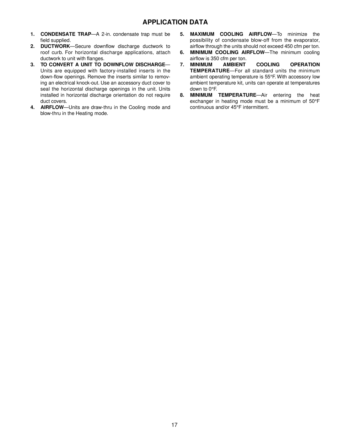
582A specifications
The Bryant 582A is a notable model in the realm of air conditioning and heating systems, designed to offer enhanced comfort, energy efficiency, and reliability. As a part of Bryant's extensive line of HVAC solutions, the 582A embodies cutting-edge technology and engineering designed to meet the needs of modern homeowners.One of the prominent features of the Bryant 582A is its high efficiency. With SEER ratings that can reach up to 16, this model ensures that homeowners experience lower energy bills while enjoying consistent temperature control. The system is designed to operate efficiently even in extreme weather conditions, highlighting its versatility for various climates.
At the core of the Bryant 582A is its advanced two-stage compressor technology. This feature enables the unit to run at lower capacities during mild weather, thereby conserving energy while still providing the necessary cool air. During hotter days, the system automatically ramps up to its full capacity, ensuring that it can effectively manage the heat. This two-stage operation also contributes to quieter performance and improved humidity control, making the indoor environment more comfortable.
The Bryant 582A boasts a durable construction, featuring a galvanized steel cabinet that is designed to withstand the elements. The unit is coated with a weather-resistant finish, which is essential for maintaining its integrity and appearance over time. Additionally, the model is designed with maintenance in mind. The easy-access panels allow for simplified service, ensuring that routine maintenance can be performed without hassle.
Technologically, the Bryant 582A includes an integrated smart thermostat option, allowing homeowners to control their HVAC system remotely. This feature not only adds convenience but also enhances energy savings by allowing users to adjust settings based on their schedules. Furthermore, the system is compatible with Bryant's Evolution control system, which provides advanced communication between indoor and outdoor units, optimizing performance.
In terms of indoor air quality, the Bryant 582A can be paired with various air purification options, ensuring that the air circulating throughout the home is clean and free from allergens. This capability makes it a valuable addition for those who prioritize health and well-being in their living environment.
Overall, the Bryant 582A stands out as an efficient, reliable, and technologically advanced HVAC solution. Its combination of energy-saving features, durable construction, and innovative controls positions it as a leading choice for homeowners seeking comfort and efficiency in their heating and cooling systems. Investing in the Bryant 582A means ensuring year-round comfort, cost savings, and enhanced indoor air quality for your home.
