APPLICATION DATA
1.Unit selection
Select equipment to either match or be slightly less than an- ticipated peak load. This provides better humidity control, fewer unit cycles, and less
For units used in spaces with high sensible loads, base equipment selection on unit sensible load, not on total an- ticipated load. Adjust for anticipated room wet bulb tem- perature to avoid undersizing equipment.
For heat pump systems, heating load using outdoor air must be checked in addition to cooling load. Heating load of outdoor air can greatly reduce heating capability.
For heat pump systems, heating and cooling design loads must both be checked.
When selecting equipment which has outdoor air intro- duced into the unit, determine the mix conditions of room air and outdoor air at design conditions. The cooling capacity tables in this literature are based on 80 F edb. Adjust for ac- tual
2.Unit combinations and coil mixed matches
The 538A, 538C, 538D, and 538S units are the only units approved for use with the 619E
3.Unit mounting (outdoor)
a.Unit leveling Ð For reliable operation, units should be level in all planes.
b.Clearance Ð Adequate clearance must be provided for air¯ow. See dimensional drawings for proper clear- ances. The outdoor units are designed for
c.Unit location Ð Cooling units may be stacked 2 high. Units may be wall mounted, pad mounted at ground level, roof mounted, mounted on or under a deck, or mounted on a patio. Be sure water drainage from roof will not drain directly onto the unit.
NOTE: If stacking units is desired (538A, 538C, 538S only),
If 018, 024, 048 units are being mounted near a wall, the
4.Unit mounting (indoor)
a.Unit leveling Ð For reliable operation, units should be level in all planes.
b.Clearance Ð Provide adequate clearance for air¯ow. The unit return and discharge should not be obstructed by furniture, curtains, or anything which may cause unit short cycling or air recirculation. See base unit dimen- sional drawings on pages 13 and 14 for required clearances.
c.Unit location Ð When selecting unit location, select a location which will provide the best air circulation for the room.
Position units as high as possible on the wall for best air circulation. Allow adequate clearances above the unit for servicing (removing unit covers). Place the unit in the middle (horizontally) of the wall selected (if possible). Select an outside wall if available to make piping easier, and place the unit so it faces the normal location of room occupants.
5.Mounting template
The fan coil units are furnished with a mounting template to mark the location of the mounting brackets, wiring, and re- frigeration hole locations.
6.Support
Adequate support must be provided to support the weight of all fan coils. Refer to the Speci®cation tables on page 8 for fan coil weights, and the base unit dimensional drawings on pages 13 and 14 for the location of mounting brackets.
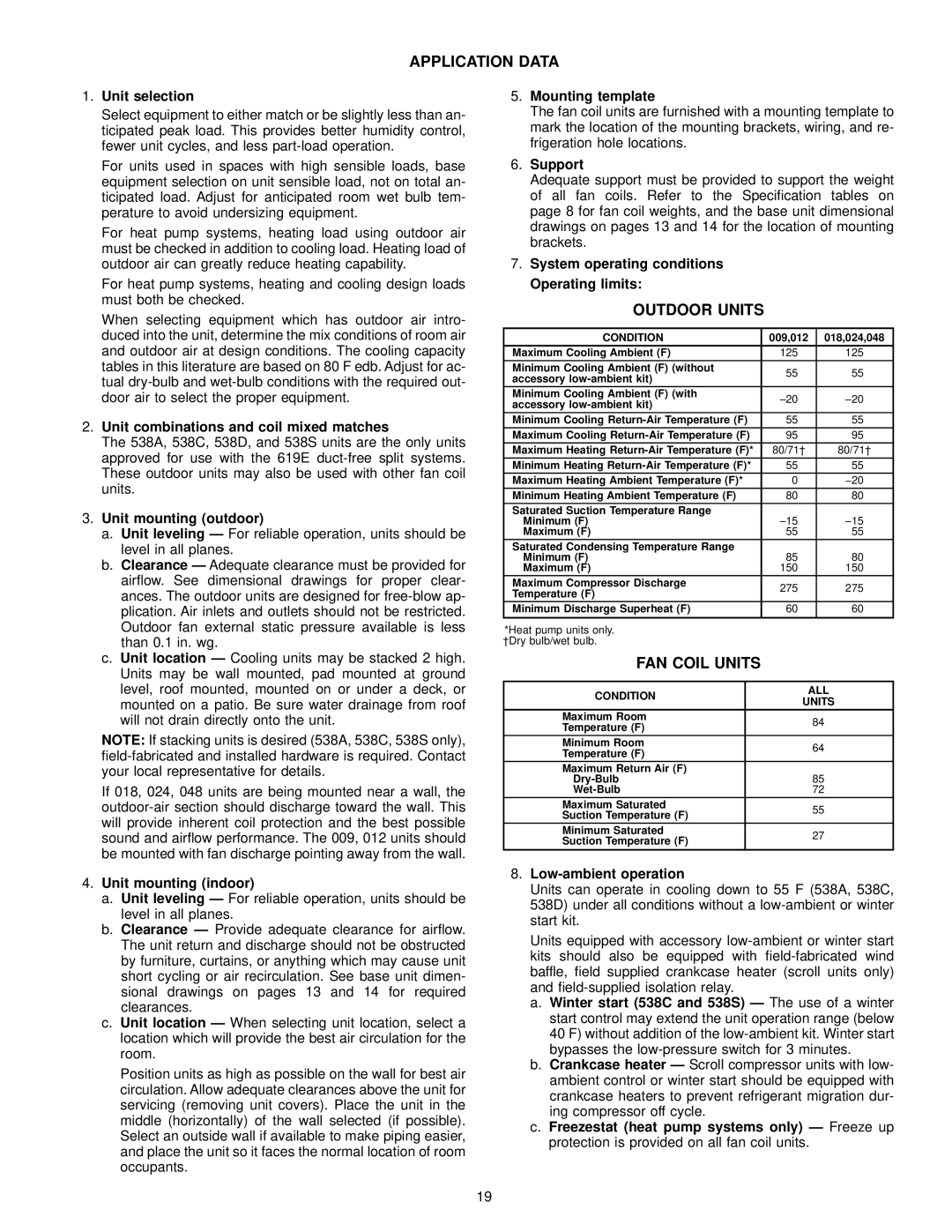
7.System operating conditions Operating limits:
OUTDOOR UNITS
CONDITION | 009,012 | 018,024,048 | |
Maximum Cooling Ambient (F) | 125 | 125 | |
Minimum Cooling Ambient (F) (without | 55 | 55 | |
accessory | |||
|
| ||
Minimum Cooling Ambient (F) (with | ±20 | ±20 | |
accessory | |||
|
| ||
Minimum Cooling | 55 | 55 | |
Maximum Cooling | 95 | 95 | |
Maximum Heating | 80/71² | 80/71² | |
Minimum Heating | 55 | 55 | |
Maximum Heating Ambient Temperature (F)* | 0 | −20 | |
Minimum Heating Ambient Temperature (F) | 80 | 80 | |
Saturated Suction Temperature Range |
|
| |
Minimum (F) | ±15 | ±15 | |
Maximum (F) | 55 | 55 | |
Saturated Condensing Temperature Range |
|
| |
Minimum (F) | 85 | 80 | |
Maximum (F) | 150 | 150 | |
Maximum Compressor Discharge | 275 | 275 | |
Temperature (F) | |||
|
| ||
Minimum Discharge Superheat (F) | 60 | 60 | |
|
|
| |
*Heat pump units only. |
|
| |
²Dry bulb/wet bulb. |
|
| |
FAN COIL UNITS |
|
|
CONDITION | ALL | |
UNITS | ||
| ||
Maximum Room | 84 | |
Temperature (F) | ||
| ||
Minimum Room | 64 | |
Temperature (F) | ||
| ||
Maximum Return Air (F) |
| |
85 | ||
72 | ||
Maximum Saturated | 55 | |
Suction Temperature (F) | ||
| ||
Minimum Saturated | 27 | |
Suction Temperature (F) | ||
|
8.Low-ambient operation
Units can operate in cooling down to 55 F (538A, 538C, 538D) under all conditions without a
Units equipped with accessory
a.Winter start (538C and 538S) Ð The use of a winter start control may extend the unit operation range (below 40 F) without addition of the
b.Crankcase heater Ð Scroll compressor units with low- ambient control or winter start should be equipped with crankcase heaters to prevent refrigerant migration dur- ing compressor off cycle.
c.Freezestat (heat pump systems only) Ð Freeze up protection is provided on all fan coil units.
19