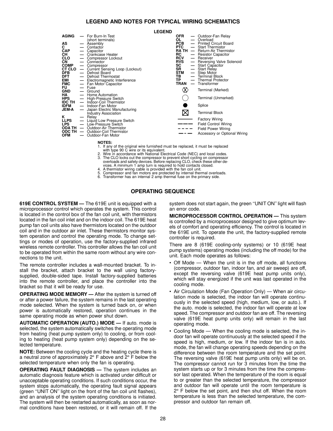
LEGEND AND NOTES FOR TYPICAL WIRING SCHEMATICS
LEGEND
AGING | Ð | For | OFR | Ð | |
|
| (short terminals) | OL | Ð Overload | |
AS | Ð Assembly | PCB | Ð Printed Circuit Board | ||
C | Ð Contactor | PTC | Ð Start Thermistor | ||
CAP | Ð | Capacitor | RA TH | Ð | |
CH | Ð Crankcase Heater | RC | Ð Resistor Capacitor | ||
CLO | Ð | Compressor Lockout | RCV | Ð | Receiver |
CN | Ð Connector | RVS | Ð Reversing Valve Solenoid | ||
COMP | Ð Compressor | SC | Ð Start Capacitor | ||
CT CLO | Ð Current Sensing Loop (Lockout) | SR | Ð | Start Relay | |
DFB | Ð | Defrost Board | STM | Ð | Step Motor |
DFT | Ð | Defrost Thermostat | TB | Ð | Terminal Block |
EMI | Ð | Electromagnetic Interference | TP | Ð | Thermal Protector |
FMC | Ð | Fan Motor Capacitor | TRAN | Ð | Transformer |
FU | Ð | Fuse |
|
| Terminal (Marked) |
GND | Ð Ground |
|
| ||
HA | Ð Home Automation |
|
| Terminal (Unmarked) | |
HPS | Ð |
|
| ||
IDC TH | Ð |
|
| Splice | |
IDFM | Ð |
|
| ||
Ð | Japan Electric Manufacturing |
|
| Terminal Block | |
|
| Industry Association |
|
| |
K | Ð Relay |
|
| Factory Wiring | |
LLPS | Ð Liquid Low Pressure Switch |
|
| ||
|
| Field Control Wiring | |||
LPS | Ð |
|
| ||
ODA TH | Ð |
|
| Field Power Wiring | |
ODC TH | Ð |
|
| Accessory or Optional Wiring | |
OFM | Ð |
|
| ||
|
|
| |||
NOTES:
1.If any of the original wire furnished must be replaced, it must be replaced with type 90 C wire or its equivalent.
2.Wire in accordance with National Electrical Code (NEC) and local codes.
3.The CLO locks out the compressor to prevent short cycling on compressor overloads and safety devices. Before replacing CLO, check these other de- vices. A minimum 1 amp turn is required to hold contacts closed.
4.A thermistor wiring cable is provided with the fan coil unit.
5.Compressor and fan motors are protected by internal thermal overloads.
6.Transformer has an internal 2 amp thermal fuse on the primary side.
OPERATING SEQUENCE
619E CONTROL SYSTEM Ð The 619E unit is equipped with a microprocessor control which operates the system. This control is located in the control box of the fan coil unit, with thermistors located in the fan coil inlet and on the indoor coil. The 619E heat pump fan coil units also have thermistors located on the outdoor coil and in the outdoor air inlet. These thermistors monitor sys- tem operation and control the operating mode. To change set- tings or modes of operation, use the
The remote controller includes a
OPERATING MODE MEMORY Ð After the system is turned off or after a power failure, the system remains in the last operating mode selected. When the system is turned back on, or when power is automatically restored, operation continues in the same operating mode as when power shut down.
AUTOMATIC OPERATION (AUTO.) MODE Ð If auto. mode is selected, the system automatically switches the operating mode from heating (heat pump system only) to cooling, or from cool- ing to heating (heat pump system only) depending on the se- lected temperature.
NOTE: Between the cooling cycle and the heating cycle there is
a neutral zone of approximately 2° F above and 2° F below the selected temperature when only the fan is operating.
OPERATING FAULT DIAGNOSIS Ð The system includes an automatic diagnosis feature which is activated under difficult or unacceptable operating conditions. If such conditions occur, the system stops automatically, the operating fault signal appears (green ``UNIT ON'' light on the front of the fan coil unit ¯ashes), and an analysis of the system operating conditions is initiated. The system will then be restarted automatically, as soon as nor- mal conditions have been restored, or it will remain off. If the
system does not start again, the green ``UNIT ON'' light will ¯ash an error code.
MICROPROCESSOR CONTROL OPERATION Ð This system is controlled by a microprocessor designed to give optimum lev- els of comfort and operating efficiency. The control is located in the 619E unit. To operate the unit, the
There are 8 (619E
·Off Mode Ð When the unit is in the off mode, all functions (compressor, outdoor fan, indoor fan, and air sweep) are off, except the reversing valve (619E heat pump units only), which will stay energized if the unit was last operated in the cooling mode.
·Air Circulation Mode (Fan Operation Only) Ð When air circu- lation mode is selected, the indoor fan will operate continu- ously in the selected speed (high, medium, low, or auto.). If the auto. mode is selected, the indoor fan will operate at low speed. The compressor and outdoor fan are off. The reversing valve (619E heat pump units only) will remain in the last operating mode.
·Cooling Mode Ð When the cooling mode is selected, the in- door fan will operate continuously at the selected speed if the speed is high, medium, or low. If the indoor fan is in auto. mode, the fan will change operating speeds depending on the difference between the room temperature and the set point. The reversing valve (619E heat pump units only) will be on. The compressor cannot run for 3 minutes from the time the system starts up or for 3 minutes from the time the compres- sor last operated. When the temperature of the room is equal to or greater than the selected temperature, the compressor and outdoor fan will operate until the room temperature is 2° F below the set point, and then shut off. When the room temperature is less than the selected temperature, the com- pressor and outdoor fan remain off.
28