TEMPERATURE PROBE
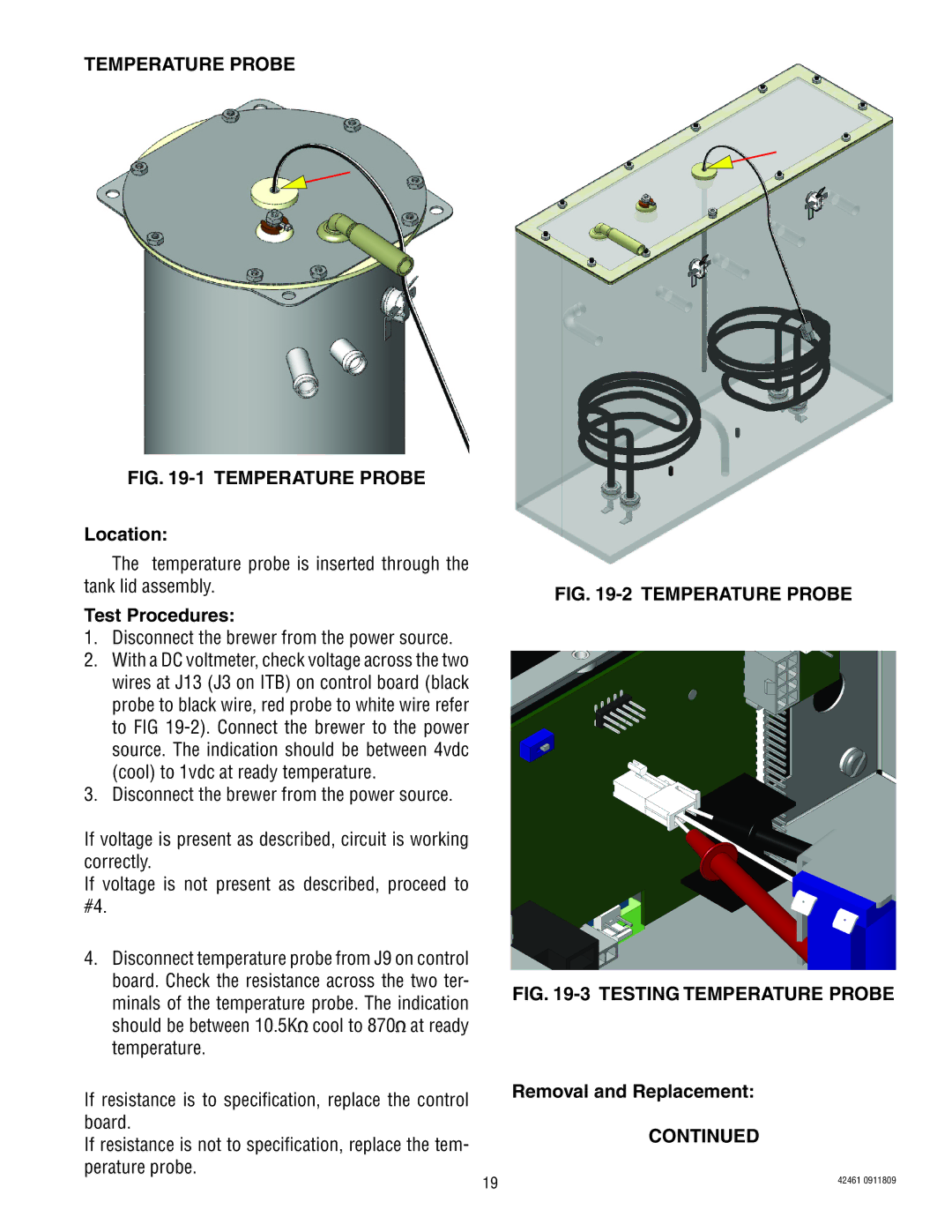
FIG. 19-1 TEMPERATURE PROBE
Location:
The temperature probe is inserted through the tank lid assembly.
Test Procedures:
1.Disconnect the brewer from the power source.
2.With a DC voltmeter, check voltage across the two wires at J13 (J3 on ITB) on control board (black probe to black wire, red probe to white wire refer to FIG
3.Disconnect the brewer from the power source.
If voltage is present as described, circuit is working correctly.
If voltage is not present as described, proceed to #4.
4.Disconnect temperature probe from J9 on control board. Check the resistance across the two ter- minals of the temperature probe. The indication should be between 10.5K![]() cool to 870
cool to 870![]() at ready temperature.
at ready temperature.
If resistance is to specification, replace the control board.
If resistance is not to specification, replace the tem- perature probe.
FIG. 19-2 TEMPERATURE PROBE
FIG. 19-3 TESTING TEMPERATURE PROBE
Removal and Replacement:
CONTINUED
19 | 42461 0911809 |
|