SERVICE (cont.)
0000(2).25716 0004(4).02328
0000.25713 0001(10).01311
P739
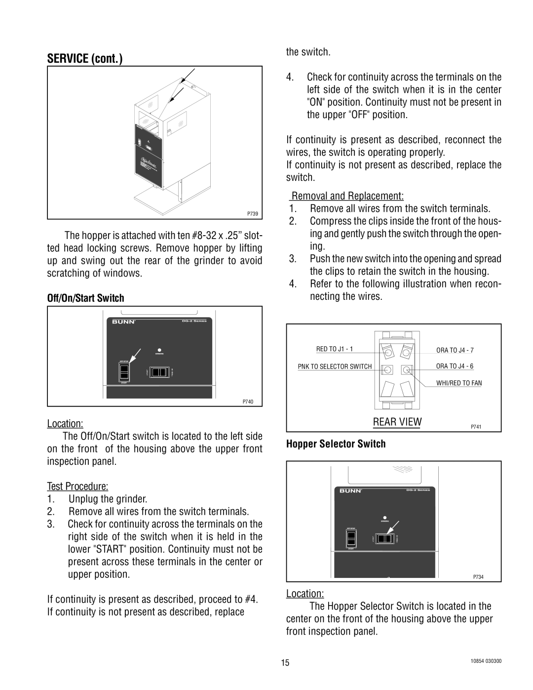
The hopper is attached with ten
Off/On/Start Switch
P740
Location:
The Off/On/Start switch is located to the left side on the front of the housing above the upper front inspection panel.
Test Procedure:
1.Unplug the grinder.
2.Remove all wires from the switch terminals.
3.Check for continuity across the terminals on the right side of the switch when it is held in the lower "START" position. Continuity must not be present across these terminals in the center or upper position.
If continuity is present as described, proceed to #4. If continuity is not present as described, replace
the switch.
4.Check for continuity across the terminals on the left side of the switch when it is in the center "ON" position. Continuity must not be present in the upper "OFF" position.
If continuity is present as described, reconnect the wires, the switch is operating properly.
If continuity is not present as described, replace the switch.
Removal and Replacement:
1.Remove all wires from the switch terminals.
2.Compress the clips inside the front of the hous- ing and gently push the switch through the open- ing.
3.Push the new switch into the opening and spread the clips to retain the switch in the housing.
4.Refer to the following illustration when recon- necting the wires.
RED TO J1 - 1 |
| ORA TO J4 - 7 |
PNK TO SELECTOR SWITCH |
| ORA TO J4 - 6 |
|
| WHI/RED TO FAN |
| REAR VIEW | P741 |
|
|
Hopper Selector Switch
P734
Location:
The Hopper Selector Switch is located in the center on the front of the housing above the upper front inspection panel.
15 | 10854 030300 |
|