7)Start the boiler using the lighting instructions on page 49. After the boiler is powered up, it should go through the following sequence.
Sequence | Display | Meaning |
1 | U.125 or Blank | Checking internal software |
2 | 0.SWT | Boiler in standby. SWT = Supply Water Temp. No call for heat. |
(After call for heat from heating thermostat) | ||
3 | A.SWT | |
4 | 5.SWT | Blower and circulator on. Checking for adequate air flow. |
5 | 1.SWT | Prepurge |
6 | 2.SWT | Trial for ignition |
7 | 3.SWT | Flame established. Boiler responding to a call for heat. |
8)Upon initial
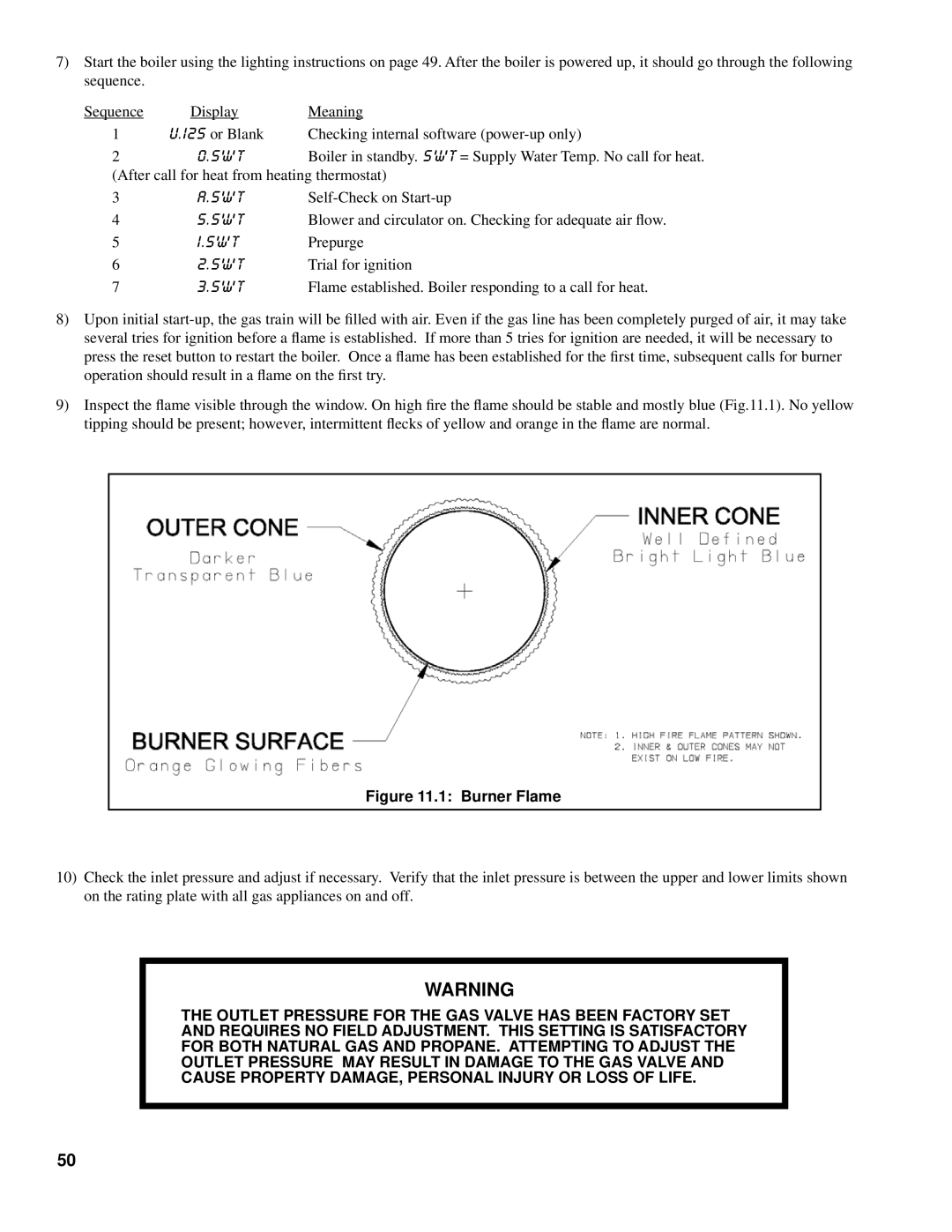
9)Inspect the flame visible through the window. On high fire the flame should be stable and mostly blue (Fig.11.1). No yellow tipping should be present; however, intermittent flecks of yellow and orange in the flame are normal.
Figure 11.1: Burner Flame
10)Check the inlet pressure and adjust if necessary. Verify that the inlet pressure is between the upper and lower limits shown on the rating plate with all gas appliances on and off.
WARNING
THE OUTLET PRESSURE FOR THE GAS VALVE HAS BEEN FACTORY SET
AND REQUIRES NO FIELD ADJUSTMENT. THIS SETTING IS SATISFACTORY
FOR BOTH NATURAL GAS AND PROPANE. ATTEMPTING TO ADJUST THE
OUTLET PRESSURE MAY RESULT IN DAMAGE TO THE GAS VALVE AND
CAUSE PROPERTY DAMAGE, PERSONAL INJURY OR LOSS OF LIFE.
50