Manuals
/
Burnham
/
Kitchen Appliance
/
Ventilation Hood
Burnham
101008-01R1-2/07
manual
Wall Mounting Hole Locations
Models:
101008-01R1-2/07
1
8
80
80
Download
80 pages
59.55 Kb
5
6
7
8
9
10
11
12
Troubleshooting
Specifications
Install
Parts list
Wiring Connections Diagram
Wiring
Warranty
Dimension
Maintenance
Outdoor Reset Curve
Page 8
Image 8
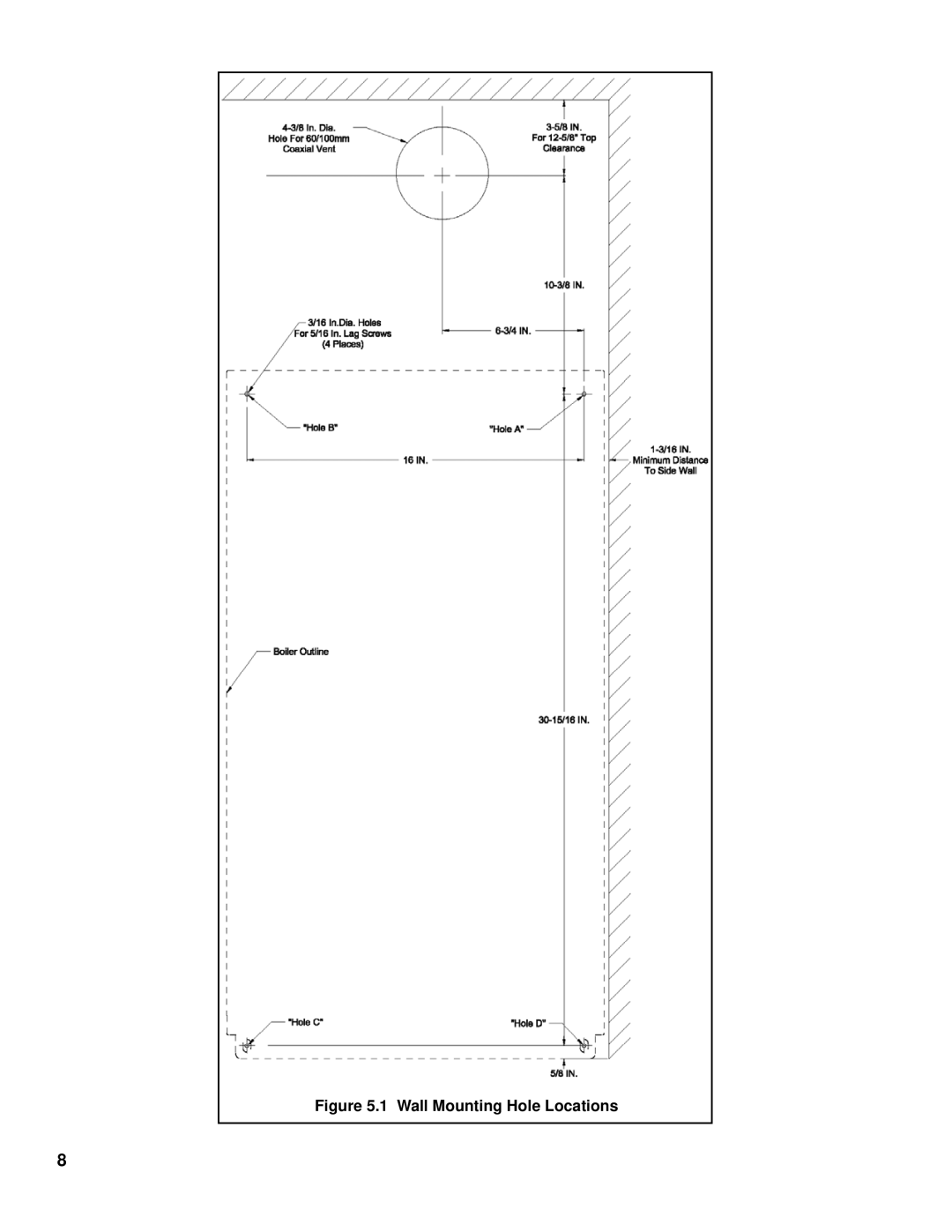
Figure 5.1 Wall Mounting Hole Locations
8
Page 7
Page 9
Page 8
Image 8
Page 7
Page 9
Contents
Freedom
Table of Contents
Specifications
Product Description
II Specifications
Maximum Vent Lengths
III Before Installing
IV Locating the Boiler
Clearances To Combustible Or Non-combustible Material
Clearances from Vent Piping to Combustible Construction
Floor Mounting
Mounting The Boiler
Wall Mounting
Wall Mounting Hole Locations
Boiler Mounting/Hardware
VI Air for Ventilation
Page
VII Venting
Vent System Design
Page
Summary of Horizontal Venting Options
Or PVC
Horizontal Concentric Venting Vent Option
U.S. Boiler Concentric Vent Components Vent Option
Size Vent
6c Positioning Vent Terminal Under Overhangs
VENT/ AIR Intake Fitting Equivalent Length
Summary of Vertical Venting Options
Roof
Removing an Existing Boiler From a Common Chimney
Never Common Vent a FCM Boiler with Other Appliances
Assembly of U.S. Boiler 60/100mm Concentric Venting
11 Dimension L
12 Cutting Outer Pipe
14 Preparing Terminal Section for Installation in the Wall
Assembly of Stainless Steel Venting
16 Installation of Stainless Steel Vent Collar
17a Star-34 Connection to Vent Collar
18 Z-Vent III Connection to Vent Collar
19 SAF-T Vent EZ Seal Connection to Vent Collar
20 FasNSeal Connection to Vent Collar
Condensate Trap and Drain Line
21 Condensate Piping Arrangement
Viii Gas Piping
Gas Connection To Boiler
General System Piping Precautions
IX System Piping
System Design
Flow Requirements Through Boiler
Method 1 Primary/Secondary Piping
Piping Method #1 Heat Only
Piping Method #1 Heat + Indirect Water Heater
4b Piping Method #1 Indirect Water Heater Loop Piping Shaded
Pipe and Circulator Sizing for Boiler Loop
Pipe and Circulator Sizing for Indirect Water Heater Loop
Fitting Equivalent Lengths
Standard Piping Installation Requirements
Boiler Head Loss
Piping for Special Situations
11 Chiller Piping
Wiring
Wiring Connections Diagram
Ladder Diagram
Page
XI Start-up and Checkout
Never Attempt to Fill a HOT Empty Boiler
Water Quality and Boiler Water Additives
FCM Series Lighting and Operating Instructions
SWT
Gas Valve Detail
Typical CO2/O2 Combustion Readings Range
Page
Normal Display In Standby Mode
XII Operation
Page
Basic Menu Tree
Boiler Status
First Digit Boiler Status
Outdoor Reset Curve
XIII. Service and Maintenance
Page
XIV. Troubleshooting
No Error Code Displayed
Soft Lockout Codes Displayed
Code Condition Possible Causes
Hard Lockout Codes Displayed
XV Parts
Page
Parts List
KEY Description
Page
Parts List
Page
Page
Page
DISP4D
150 151 152 153 154 155
156 157 158 159 160 161
162
Page
Page
Page
Page
Page
Limited Warranty
Top
Page
Image
Contents