VIII. System Start-up
A.Safe operation and other performance criteria were met with gas manifold and control assembly provided on boiler when boiler underwent tests specified in American National Standard for
B. FILL ENTIRE HEATING SYSTEM WITH WATER and vent air from system. Use the following procedure on a Series Loop System equipped with zone valves. (See Figure 4).
1.Close isolation valve in boiler supply piping.
2.Isolate all circuits by closing zone valves or balancing valves.
3.Attach a hose to hose bib located just below isolation valve in boiler supply piping. (Note - Terminate hose in five gallon bucket or at a suitable floor drain or outdoor area).
4.Starting with one circuit, open zone valve.
5.Open hose bib.
6.Open manual fill valve
7.Allow water to overflow from bucket until discharge from hose is bubble free for 30 seconds.
8.Open zone valve to the second zone to be purged, then close the first. Repeat this step until all zones have been purged, but always have one zone open. At completion, open all zone valves.
9.Close hose bib, continue filling the system until the pressure gauge reads between 12 and 15 psi. Close fill valve.
WARNING
DO NOT install an automatic fill valve with this boiler.
10.Open isolation valve in boiler supply piping.
11.Remove hose from hose bib.
C. Prepare to check operation.
1.Obtain gas heating value (in BTU per cubic foot) from gas supplier.
2.Connect manometer to pressure tap on gas valve. Use 1/8 NPT tapping provided.
3.Temporarily turn off all other
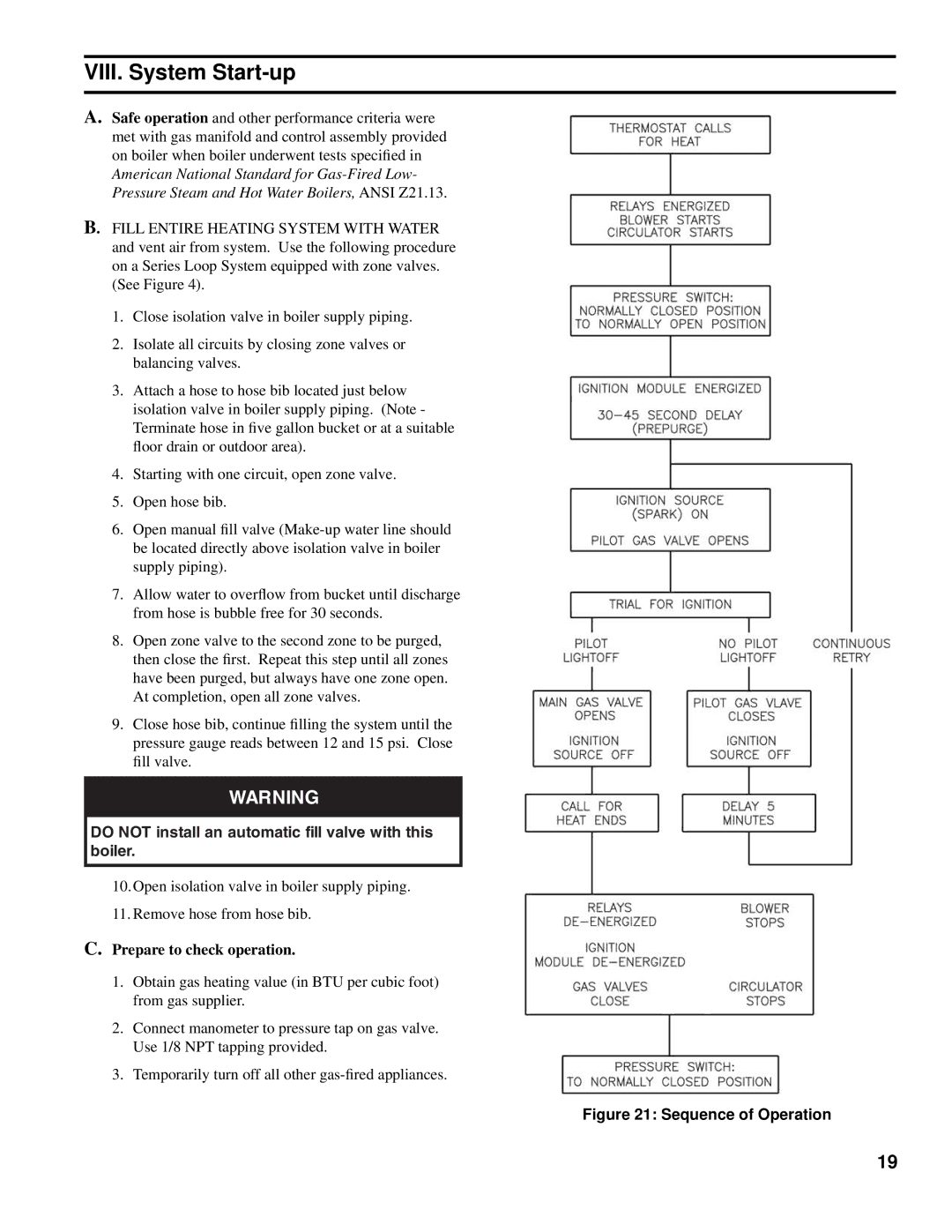
Figure 21: Sequence of Operation
19