Table 7: Burnham Vent System Components
Burnham | Burnham | Equivalent | |
Vent System | Part | ||
Feet of Pipe | |||
Component | Number | ||
| |||
|
|
| |
3" Dia. Pipe x 1 Ft | 8116296U | 1 | |
|
|
| |
3" Dia. Pipe x 3 Ft | 8116298U | 3 | |
|
|
| |
3" Dia. Pipe x 5 Ft | 8116300U | 5 | |
|
|
| |
|
| Equal to | |
3" Dia. Pipe x Adjustable | 8116319U | Installed Length | |
|
| (1.06 to 1.64) | |
|
|
| |
3" Dia. 90° Elbow | 8116294U | 5 | |
|
|
| |
3" Dia. 45° Elbow | 8116292U | 5 | |
|
|
| |
3" Dia. Horizontal Drain Tee | 8116302U | ½ | |
|
|
| |
3" Dia. Vertical Drain Tee | 8116304U | 7½ | |
|
|
| |
3" Single Wall Thimble | 8116116 | ||
|
|
| |
3" Double Wall Thimble | 8116115 | ||
|
|
|
4.Do not install venting system components on the exterior of the building except as specifically required by these instructions.
5.Thickness of exterior walls through which
B.Removal of Existing Boiler. For installations not involving the replacement of an existing boiler, proceed to Step C.
When an existing boiler is removed from a common venting system, the common venting system is likely to be too large for proper venting of the remaining appliances. At the time of removal of an existing boiler, the following steps shall be followed with each appliance remaining connected to the common venting system placed in operation, while the other appliances remaining connected to the common venting system are not in operation:
1.Seal any unused openings in the common venting system.
2.Visually inspect the venting system for proper size and horizontal pitch and determine there is no blockage or restriction, leakage, corrosion, and other deficiencies which could cause an unsafe condition.
3.Insofar as is practical, close all building doors and windows and all doors between the space in which the appliances remaining connected to the common venting system are located and other spaces of the building. Turn on clothes dryers and any appliance not connected to the common venting system. Turn on any exhaust fans, such as
4.Place in operation the appliance being inspected. Follow the Lighting (or Operating) Instructions. Adjust thermostat so appliance will operate continuously.
5.Test for spillage at the drafthood relief opening after 5 minutes of main burner operation. Use the flame of a match or candle, or smoke from a cigarette, cigar or pipe.
6.After it has been determined that each appliance remaining connected to the common venting system properly vents when tested as outlined above, return doors, windows, exhaust fans, fireplace dampers and any other gas burning appliance to their previous conditions of use.
7.Any improper operation of the common venting system should be corrected so the installation conforms with the National Fuel Gas Code, ANSI Z223.1 and/or CAN/CGA B149, Installation Codes. When resizing any portion of the common venting system, the common venting system should be resized to approach the minimum size as determined using the appropriate tables in Part 11 in the National Fuel Gas Code, ANSI Z223.1 and/or CAN/CGA B149, Installation Codes.
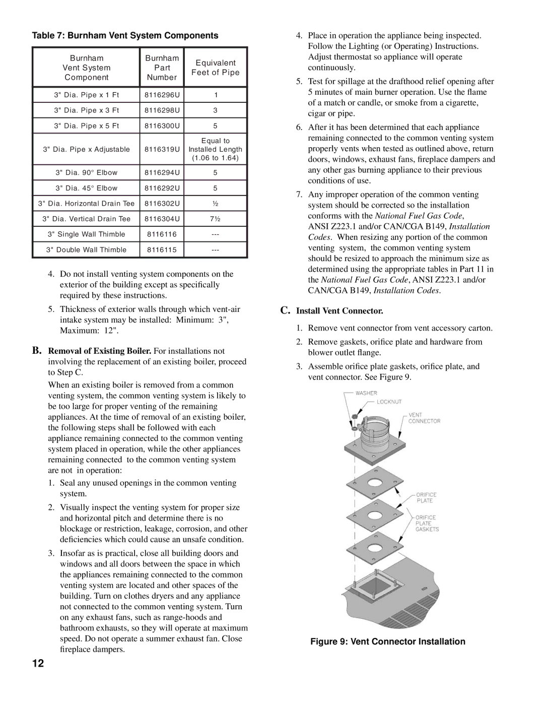
C.Install Vent Connector.
1.Remove vent connector from vent accessory carton.
2.Remove gaskets, orifice plate and hardware from blower outlet flange.
3.Assemble orifice plate gaskets, orifice plate, and vent connector. See Figure 9.
Figure 9: Vent Connector Installation
12