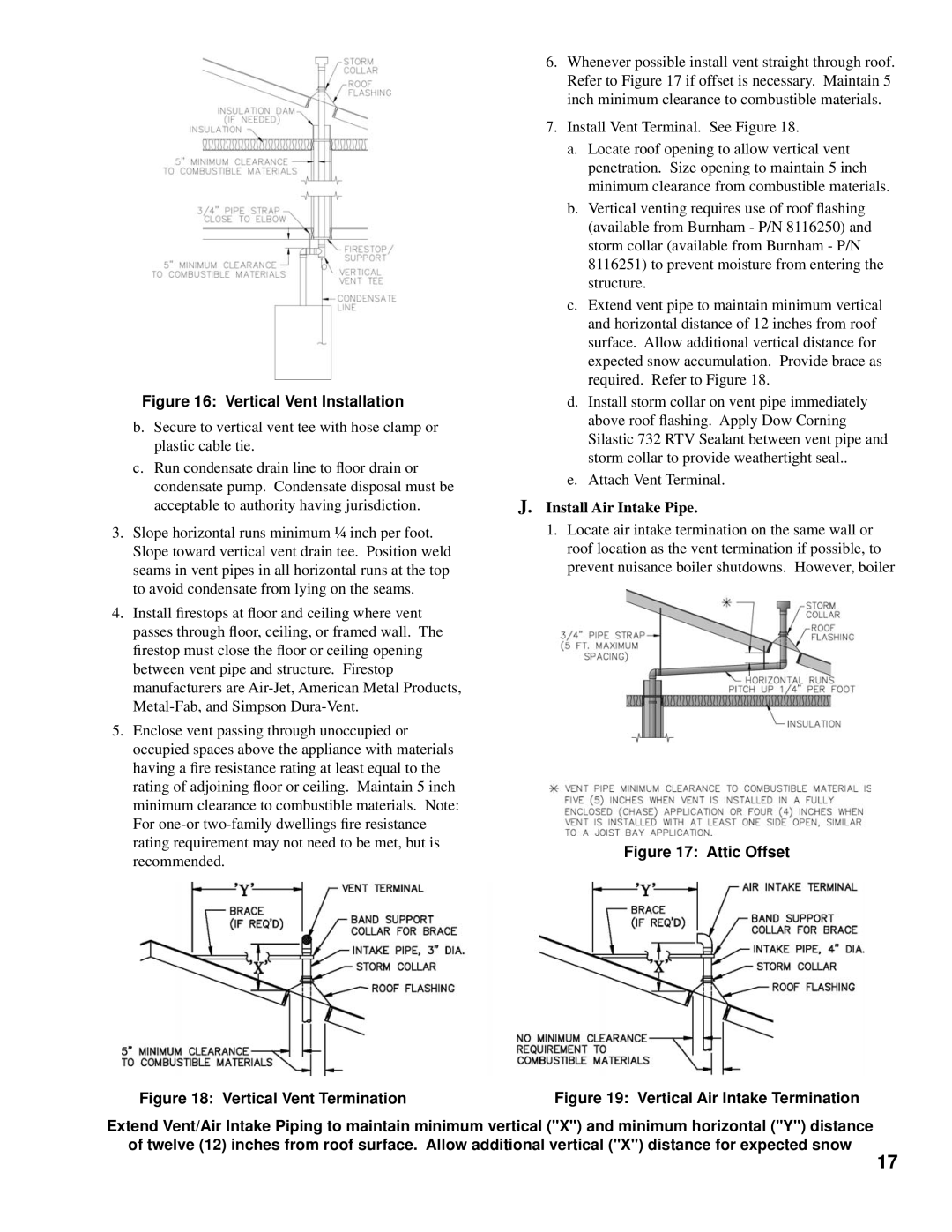
Figure 16: Vertical Vent Installation
b.Secure to vertical vent tee with hose clamp or plastic cable tie.
c.Run condensate drain line to floor drain or condensate pump. Condensate disposal must be acceptable to authority having jurisdiction.
3.Slope horizontal runs minimum ¼ inch per foot. Slope toward vertical vent drain tee. Position weld seams in vent pipes in all horizontal runs at the top to avoid condensate from lying on the seams.
4.Install firestops at floor and ceiling where vent passes through floor, ceiling, or framed wall. The firestop must close the floor or ceiling opening between vent pipe and structure. Firestop manufacturers are
5.Enclose vent passing through unoccupied or occupied spaces above the appliance with materials having a fire resistance rating at least equal to the rating of adjoining floor or ceiling. Maintain 5 inch minimum clearance to combustible materials. Note: For
6.Whenever possible install vent straight through roof. Refer to Figure 17 if offset is necessary. Maintain 5 inch minimum clearance to combustible materials.
7.Install Vent Terminal. See Figure 18.
a.Locate roof opening to allow vertical vent penetration. Size opening to maintain 5 inch minimum clearance from combustible materials.
b.Vertical venting requires use of roof flashing (available from Burnham - P/N 8116250) and storm collar (available from Burnham - P/N 8116251) to prevent moisture from entering the structure.
c.Extend vent pipe to maintain minimum vertical and horizontal distance of 12 inches from roof surface. Allow additional vertical distance for expected snow accumulation. Provide brace as required. Refer to Figure 18.
d.Install storm collar on vent pipe immediately above roof flashing. Apply Dow Corning Silastic 732 RTV Sealant between vent pipe and storm collar to provide weathertight seal..
e.Attach Vent Terminal.
J. Install Air Intake Pipe.
1.Locate air intake termination on the same wall or roof location as the vent termination if possible, to prevent nuisance boiler shutdowns. However, boiler
Figure 17: Attic Offset
Figure 18: Vertical Vent Termination | Figure 19: Vertical Air Intake Termination |
Extend Vent/Air Intake Piping to maintain minimum vertical ("X") and minimum horizontal ("Y") distance
of twelve (12) inches from roof surface. Allow additional vertical ("X") distance for expected snow
17
