may be installed with vertical venting and sidewall combustion air inlet if installation conditions do not allow alternate arrangement.
2.Use 4 inch diameter single wall metal pipe, fittings, firestop(s), roof flashing and storm collar available at most heating distributors.
3.Start at air intake connector. Work toward air intake terminal.
4.Maintain minimum of ¼ inch per foot slope in horizontal runs to air intake terminal. Slope down toward air intake terminal.
5.Seal all joints
6.Install air intake terminal. See Figures 14 and 19.
VII. Electrical
A.General. Install wiring and ground boiler in accordance with requirements of authority having jurisdiction, or in absence of such requirements the National Electrical Code, ANSI/NFPA 70, and/or the CSA C22.1 Electric Code.
B.Install thermostat. Locate on inside wall approximately 4 feet above floor. Do not install on outside wall, near fireplace, or where influenced by drafts or restricted air flow, hot or cold water pipes, lighting fixtures, television, or sunlight. Allow free air movement by avoiding placement of furniture near thermostat.
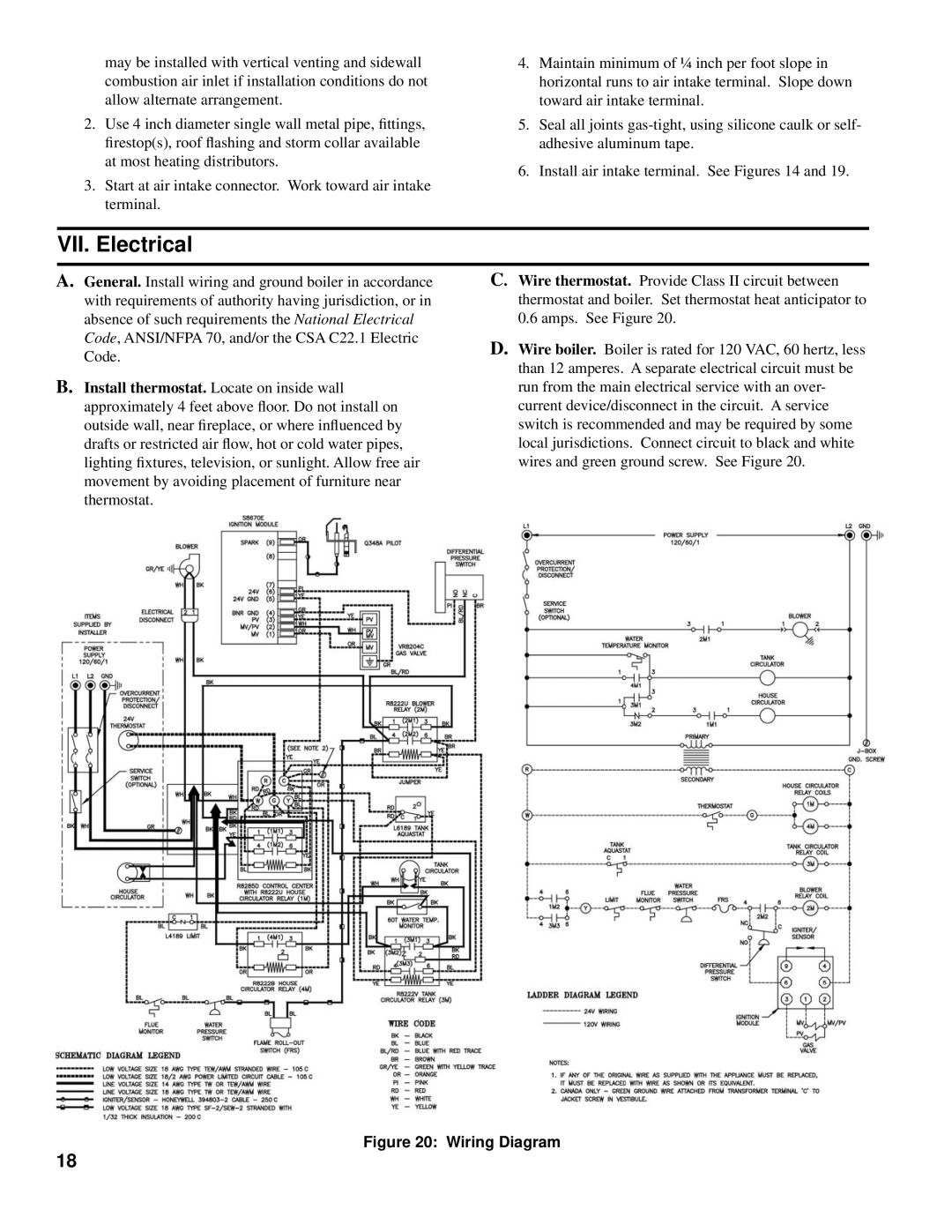
C. Wire thermostat. Provide Class II circuit between thermostat and boiler. Set thermostat heat anticipator to
0.6 amps. See Figure 20.
D.Wire boiler. Boiler is rated for 120 VAC, 60 hertz, less than 12 amperes. A separate electrical circuit must be run from the main electrical service with an over- current device/disconnect in the circuit. A service switch is recommended and may be required by some local jurisdictions. Connect circuit to black and white wires and green ground screw. See Figure 20.
Figure 20: Wiring Diagram
18