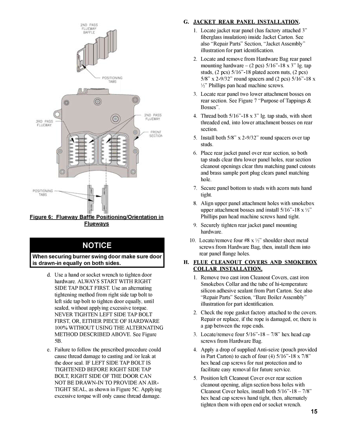
Figure 6: Flueway Baffle Positioning/Orientation in

Flueways

NOTICE

When securing burner swing door make sure door is drawn-in equally on both sides.

d.Use a hand or socket wrench to tighten door hardware. ALWAYS START WITH RIGHT SIDE TAP BOLT FIRST. Use an alternating tightening method from right side tap bolt to left side tap bolt to tighten door equally, until sealed, without applying excessive torque.

NEVER TIGHTEN LEFT SIDE TAP BOLT FIRST, OR, EITHER PIECE OF HARDWARE 100% WITHOUT USING THE ALTERNATING METHOD DESCRIBED ABOVE. See Figure 5B.

e.Failure to follow the prescribed procedure could cause thread damage to casting and /or leak at the door seal. IF LEFT SIDE TAP BOLT IS TIGHTENED BEFORE RIGHT SIDE TAP BOLT, RIGHT SIDE OF THE DOOR CAN NOT BE DRAWN-IN TO PROVIDE AN AIR- TIGHT SEAL, as shown in Figure 5C. Applying excessive torque will only cause thread damage.

G.Jacket Rear Panel Installation.

1.Locate jacket rear panel (has factory attached 3” fiberglass insulation) inside Jacket Carton. See also “Repair Parts” Section, “Jacket Assembly” illustration for part identification.

2.Locate and remove from Hardware Bag rear panel mounting hardware – (2 pcs) 5/16”-18 x 3” lg. tap studs, (2 pcs) 5/16”-18 plated acorn nuts, (2 pcs)

5/8” x 2-9/32” round spacers and (2 pcs) 5/16”-18 x ½” Phillips pan head machine screws.

3.Locate rear panel two lower attachment bosses on rear section. See Figure 7 “Purpose of Tappings &

Bosses”.

4.Thread both 5/16”-18 x 3” lg. tap studs, with short threaded end, into lower attachment bosses on rear section.

5.Install both 5/8” x 2-9/32” round spacers over tap studs.

6.Place rear jacket panel over rear section, so both tap studs clear thru lower panel holes, rear section cleanout openings clear thru matching panel cutouts and brass sample port plug clears panel matching hole.

7.Secure panel bottom to studs with acorn nuts hand tight.

8.Align upper panel attachment holes with smokebox upper attachment bosses and install 5/16”-18 x ½”

Phillips pan head machine screws hand tight.

9.Securely tighten rear jacket panel mounting hardware.

10.Locate/remove four #8 x ½” shoulder sheet metal screws from Hardware Bag, then, install them into rear panel flange holes.

H.Flue Cleanout Covers and Smokebox Collar Installation.

1.Remove two cast iron Cleanout Covers, cast iron

Smokebox Collar and the tube of hi-temperature silicon adhesive sealant from Part Carton. See also

“Repair Parts” Section, “Bare Boiler Assembly” illustration for part identification.

2.Check the rope gasket factory attached to the covers. Repair or replace, if the rope is damaged, or, there is a gap between the rope ends.

3.Locate/remove four 5/16”-18 – 7/8” hex head cap screws from Hardware Bag.

4.Apply a drop of supplied Anti-seize (pouch provided in Part Carton) to each of four (4) 5/16”-18 x 7/8” hex head cap screws for rust protection and to facilitate easy removal for future service.

5.Position left Cleanout Cover over rear section cleanout opening, align section boss holes with Cleanout Cover holes, install both 5/16”-18 – 7/8” hex head cap screws hand tight, then, alternately tighten them with open end or socket wrench.

15

Page 15
Image 15
Burnham MST513, MST288, MST396, MST629 Jacket Rear Panel Installation, Flue Cleanout Covers and Smokebox Collar Installation

MST513, MST396, MST629, MST288 specifications

The Burnham MST series, comprising models MST396, MST629, MST513, and MST288, is renowned for its robust design and exceptional performance in the boiler industry. Each model is engineered to provide optimal efficiency and reliability for residential and commercial heating applications.

The Burnham MST396 is distinguished by its high thermal efficiency and advanced combustion technology. This model features a cast iron heat exchanger which ensures superior heat retention and distribution. The MST396 is equipped with a powerful burner that allows for variable firing rates, maximizing efficiency and extending the lifespan of the unit. Additionally, it includes a built-in electronic ignition system that enhances reliability while reducing the need for frequent maintenance.

Moving to the MST629, this model is designed for larger applications needing higher output. It boasts a significant BTU input and utilizes a multi-stage burner system. This ensures optimal combustion and adapts to varying demand, providing consistent heat without wasting energy. The MST629 also incorporates enhanced insulation and an advanced flue gas venting system to improve safety and minimize energy loss.

The MST513 caters to mid-sized applications with its adaptable performance and user-friendly features. This model is notable for its compact design, making it suitable for installations with limited space. It uses a two-stage burner for efficient energy use and offers a smart control system that monitors performance in real-time. This allows users to make informed decisions about their energy consumption and maintenance needs, ultimately leading to cost savings.

Lastly, the MST288 is the smaller model in the series, ideal for homes and small businesses. Despite its size, it does not compromise on efficiency. The MST288 features a straightforward design, ensuring ease of installation and maintenance. It utilizes a single-stage burner that provides consistent heat output, making it a reliable choice for low-demand applications. The unit is also equipped with adjustable settings, allowing users to tailor their heating needs effectively.

In summary, the Burnham MST series demonstrates a remarkable blend of innovation and practicality across its models. With features like advanced burner technology, efficient heat exchangers, and smart controls, the MST396, MST629, MST513, and MST288 cater to a wide range of heating needs while prioritizing energy efficiency and user comfort. These models stand out in the market, continually setting a standard for performance and reliability in heating solutions.