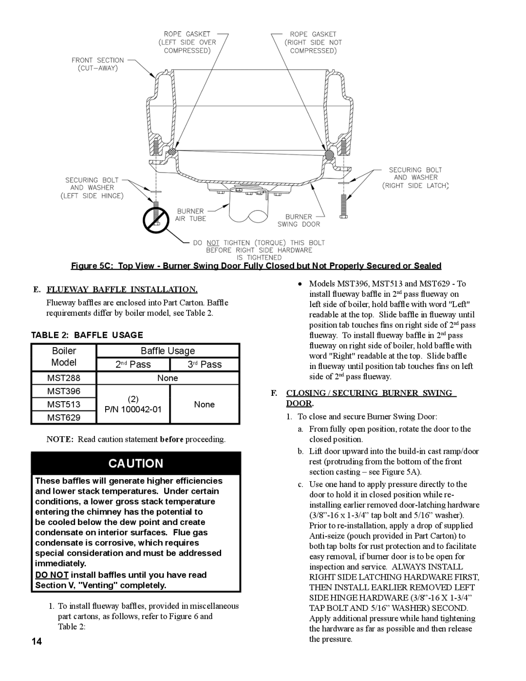
MST513, MST396, MST629, MST288 specifications
The Burnham MST series, comprising models MST396, MST629, MST513, and MST288, is renowned for its robust design and exceptional performance in the boiler industry. Each model is engineered to provide optimal efficiency and reliability for residential and commercial heating applications.The Burnham MST396 is distinguished by its high thermal efficiency and advanced combustion technology. This model features a cast iron heat exchanger which ensures superior heat retention and distribution. The MST396 is equipped with a powerful burner that allows for variable firing rates, maximizing efficiency and extending the lifespan of the unit. Additionally, it includes a built-in electronic ignition system that enhances reliability while reducing the need for frequent maintenance.
Moving to the MST629, this model is designed for larger applications needing higher output. It boasts a significant BTU input and utilizes a multi-stage burner system. This ensures optimal combustion and adapts to varying demand, providing consistent heat without wasting energy. The MST629 also incorporates enhanced insulation and an advanced flue gas venting system to improve safety and minimize energy loss.
The MST513 caters to mid-sized applications with its adaptable performance and user-friendly features. This model is notable for its compact design, making it suitable for installations with limited space. It uses a two-stage burner for efficient energy use and offers a smart control system that monitors performance in real-time. This allows users to make informed decisions about their energy consumption and maintenance needs, ultimately leading to cost savings.
Lastly, the MST288 is the smaller model in the series, ideal for homes and small businesses. Despite its size, it does not compromise on efficiency. The MST288 features a straightforward design, ensuring ease of installation and maintenance. It utilizes a single-stage burner that provides consistent heat output, making it a reliable choice for low-demand applications. The unit is also equipped with adjustable settings, allowing users to tailor their heating needs effectively.
In summary, the Burnham MST series demonstrates a remarkable blend of innovation and practicality across its models. With features like advanced burner technology, efficient heat exchangers, and smart controls, the MST396, MST629, MST513, and MST288 cater to a wide range of heating needs while prioritizing energy efficiency and user comfort. These models stand out in the market, continually setting a standard for performance and reliability in heating solutions.

