EXAMPLE NETWORKS

The interface name is a symbolic name given to the interface. For the WAN (RLAN) interface, you should use a name that describes this interface. Type Satellites for this example.

You will then be asked for the IP address for the interface. In our example, the value you should enter is 198.12.10.1. You will then be asked for the IP subnet mask value. In our example, we are using a Class C address (without any subnetwork addressing) that requires 24 bits of the address to define the network number. Therefore, press <return> to accept the default of “24” significant bits. Press <return> to accept the default packet encapsulation type (Ethernet). Press <return> to accept the default of 1500 as the MTU size. Press <return> to accept the default transmit broadcast address.

The rest of the RLAN interface information requested pertains to the Proxy ARP and, if you have not disabled RIP, the RIP feature. Accept all of the default values, or modify as needed.

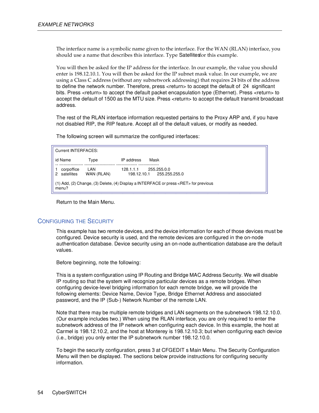
The following screen will summarize the configured interfaces:

Current INTERFACES:


id Name

Type

IP address

Mask

-- -----------------

---------------------- --------------- ---------------

1

corpoffice

LAN

128.1.1.1

255.255.0.0

2

satellites

WAN (RLAN)

198.12.10.1

255.255.255.0

(1) Add, (2) Change, (3) Delete, (4) Display a INTERFACE or press <RET> for previous menu?

Return to the Main Menu.

CONFIGURING THE SECURITY

This example has two remote devices, and the device information for each of those devices must be configured. Device security is used, and the remote devices are configured in the on-node authentication database. Device security using an on-node authentication database are the default values.

Before beginning, note the following:

This is a system configuration using IP Routing and Bridge MAC Address Security. We will disable IP routing so that the system will recognize particular devices as a remote bridges. When configuring device-level bridging information for each remote bridge, we will provide the following elements: Device Name, Device Type, Bridge Ethernet Address and associated password, and the IP (Sub-) Network Number of the remote LAN.

Note that there may be multiple remote bridges and LAN segments on the subnetwork 198.12.10.0. (Our example includes two.) When using the RLAN interface, you are only required to enter the subnetwork address of the IP network when configuring each device. In this example, the host at Carmel is 198.12.10.2, and the host at Monterey is 198.12.10.3; but when configuring each device (i.e., bridge) you only enter the IP subnetwork number 198.12.10.0.

To begin the security configuration, press 3 at CFGEDIT’s Main Menu. The Security Configuration Menu will then be displayed. The sections below provide instructions for configuring security information.

54 CyberSWITCH

Page 54
Image 54
Cabletron Systems 150 manual Return to the Main Menu

150 specifications

Cabletron Systems 150, a notable networking device in the pantheon of computer networking technology, was introduced during a pivotal period in the evolution of network infrastructure. Designed to support the rapidly growing demands of organizations, it quickly became known for its robust performance and versatility.

One of the standout features of the Cabletron Systems 150 is its ability to function as a multiport repeater and a path to high-speed network connections. This versatility means that the device can connect multiple segments of a network while maintaining the integrity and efficiency of data transmission. The device is designed for multiple data rates, accommodating both 10BASE-T and 100BASE-T technologies, making it suitable for various types of networks, from traditional Ethernet setups to more advanced Fast Ethernet configurations.

The Cabletron 150 was built using advanced technologies that allowed for increased bandwidth and reduced latency. Its ability to handle various protocols made it indispensable in environments that required seamless communication across diverse systems. Network managers appreciated the device's Layer 2 switching capabilities, which facilitated faster data flow and minimized broadcast traffic on the network, enhancing overall performance.

Another significant characteristic of the Cabletron Systems 150 is its modular design. This architecture enables users to upgrade or expand the system based on their changing networking needs, providing a future-proof solution that adapts to evolving technology landscapes. With a range of interface options, the device can support twisted pair and fiber optic connections, catering to organizations with different infrastructural preferences.

The Cabletron Systems 150 also stands out for its ease of management. Network administrators could remotely monitor and configure the device, allowing for efficient troubleshooting and maintenance. The inclusion of SNMP (Simple Network Management Protocol) capabilities further simplified network management tasks, helping IT teams ensure optimal performance.

In summary, the Cabletron Systems 150 was a pioneering networking device characterized by its multiport repeater functionality, compatibility with multiple protocols, high-speed data transmission capabilities, and modularity. It served as a reliable backbone for organizations aiming to enhance their network performance while providing scalability for future needs. The legacy of Cabletron Systems 150 continues to be felt in the networking world, reflecting the early innovations that laid the groundwork for today’s complex networking technologies.