MAKING NETWORK CONNECTIONS
12 3 4 5 6 7 8
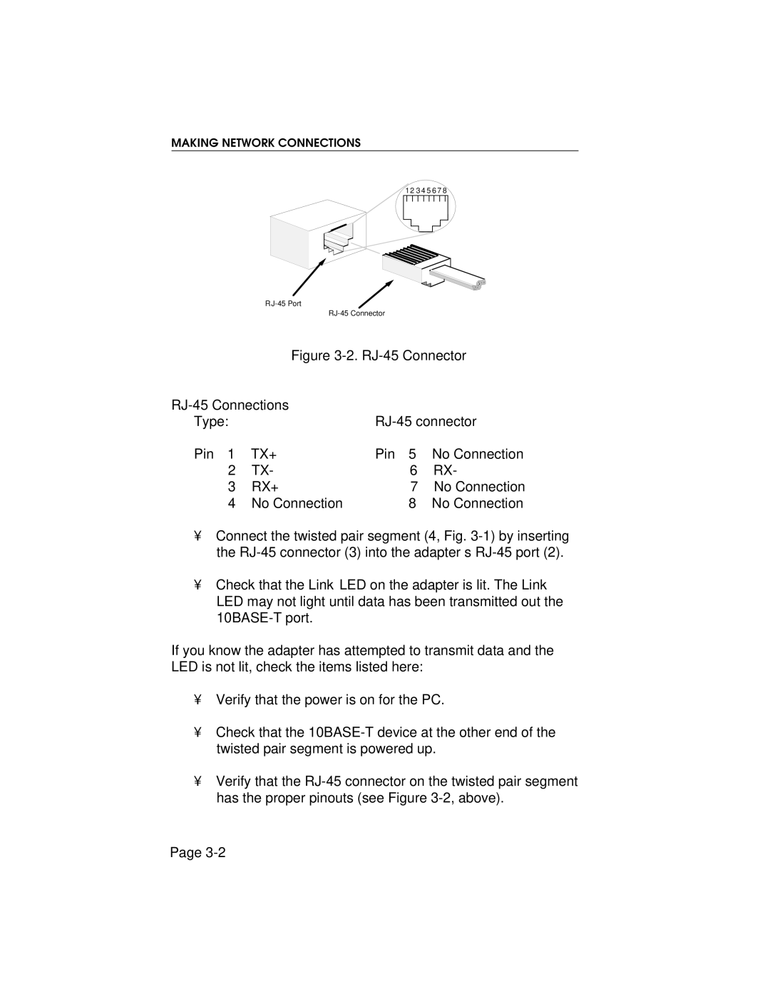
Figure 3-2. RJ-45 Connector
|
|
| |
Type: |
|
| |
Pin 1 | TX+ | Pin 5 | No Connection |
2 | TX- | 6 | RX- |
3 | RX+ | 7 | No Connection |
4 | No Connection | 8 | No Connection |
•Connect the twisted pair segment (4, Fig.
•Check that the Link LED on the adapter is lit. The Link LED may not light until data has been transmitted out the
If you know the adapter has attempted to transmit data and the LED is not lit, check the items listed here:
•Verify that the power is on for the PC.
•Check that the
•Verify that the
Page