Compresores Sin Aceite
FP2048, FP2049
Guía de diagnóstico de averías (Continuación)
Problema | Posible(s) Causa(s) | Acción a tomar | ||
Exceso de humedad en | 1. Demasiada agua en el tanque | 1. | Drene el tanque, incline el tanque para eliminar la | |
el aire de descarga |
|
| humedad | |
|
| 2. Humedad elevada | 2. | Llévelo a un área menos húmeda, utilice un filtro de |
|
|
|
| aire de línea |
|
|
|
| Nota: La condensación de agua no es una causa para |
|
|
|
| el malfuncionamiento del compresor. |
|
|
|
|
|
El compresor funciona | 1. Presostato defectuoso | 1. | Cambie el interruptor de presión | |
en forma continua y la | 2. Válvula de seguridad defectuosa | 2. | Cambie la válvula de retención con un repuesto | |
válvula de seguridad se |
|
| original | |
abre cuando aumenta |
|
|
| |
la presión |
|
|
| |
|
|
|
| |
Arranques y paradas | 1. Demasiada condensación en el | 1. | Drene con más frecuencia | |
excesivas | tanque |
|
| |
|
| 2. Conexiones flojas (accesorios, tubería, | 2. | Revise todas las conexiones con una solución de agua |
|
| etc.) |
| y jabón. Si se detecta una fuga, apriete. O quite la |
|
|
|
| conexión y aplique cinta para tuberías a las rocas y |
|
|
|
| vuelva a armar. |
Installation
(Continued)
! DANGER Do not use a grounding adapter with this product!
2.If repair or replacement of cord or plug is necessary, do not connect grounding wire to either flat blade terminal. The wire with insulation having an external surface that is green (with or without yellow stripes) is the grounding wire.
| Never connect | |
! WARNING | ||
green (or green and | ||
|
yellow) wire to a live terminal.
3. Check with a qualified electrician or |
serviceman if grounding instructions |
are not completely understood, or if in |
doubt as to whether product is |
properly grounded. Do not modify |
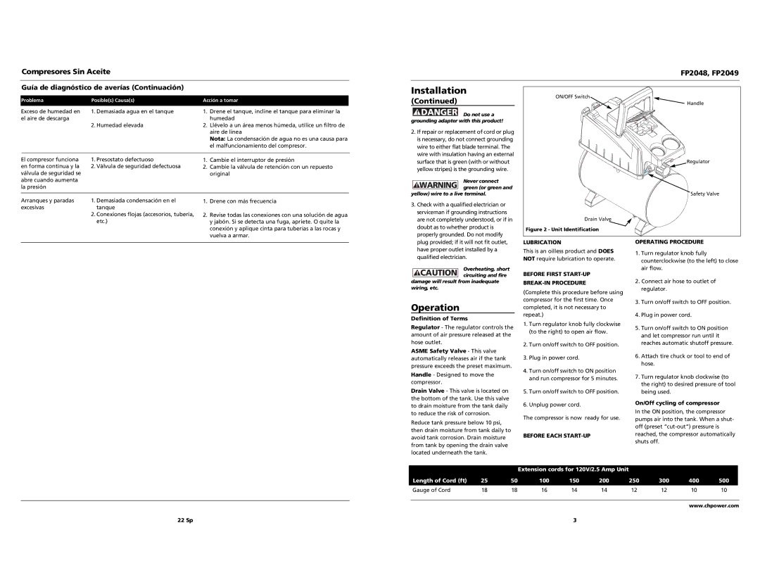
ON/OFF Switch
Handle
Regulator
Safety Valve
Drain Valve
Figure 2 - Unit Identification
plug provided; if it will not fit outlet, |
have proper outlet installed by a |
qualified electrician. |
Overheating, short ! CAUTION circuiting and fire
damage will result from inadequate wiring, etc.
Operation
Definition of Terms
Regulator - The regulator controls the amount of air pressure released at the hose outlet.
ASME Safety Valve - This valve automatically releases air if the tank pressure exceeds the preset maximum.
Handle - Designed to move the compressor.
Drain Valve - This valve is located on the bottom of the tank. Use this valve to drain moisture from the tank daily to reduce the risk of corrosion.
Reduce tank pressure below 10 psi, then drain moisture from tank daily to avoid tank corrosion. Drain moisture from tank by opening the drain valve located underneath the tank.
LUBRICATION
This is an oilless product and DOES NOT require lubrication to operate.
BEFORE FIRST START-UP
BREAK-IN PROCEDURE
(Complete this procedure before using compressor for the first time. Once completed, it is not necessary to repeat.)
1.Turn regulator knob fully clockwise (to the right) to open air flow.
2.Turn on/off switch to OFF position.
3.Plug in power cord.
4.Turn on/off switch to ON position and run compressor for 5 minutes.
5.Turn on/off switch to OFF position.
6.Unplug power cord.
The compressor is now ready for use.
BEFORE EACH START-UP
OPERATING PROCEDURE
1.Turn regulator knob fully counterclockwise (to the left) to close air flow.
2.Connect air hose to outlet of regulator.
3.Turn on/off switch to OFF position.
4.Plug in power cord.
5.Turn on/off switch to ON position and let compressor run until it reaches automatic shutoff pressure.
6.Attach tire chuck or tool to end of hose.
7.Turn regulator knob clockwise (to the right) to desired pressure of tool being used.
On/Off cycling of compressor
In the ON position, the compressor pumps air into the tank. When a shut- off (preset
|
|
| Extension cords for 120V/2.5 Amp Unit |
|
|
|
| ||
Length of Cord (ft) | 25 | 50 | 100 | 150 | 200 | 250 | 300 | 400 | 500 |
Gauge of Cord | 18 | 18 | 16 | 14 | 14 | 12 | 12 | 10 | 10 |
www.chpower.com
22 Sp | 3 |