Operating Instructions and Parts Manual

Operation (Continued)


Metal

Heat


Thickness

Setting


14 - 18 Gauge

Low


Thicker Than 14 Gauge

High

6. Rotate the Wire Speed Control to

setting number 5 to start with, then

adjust as needed after test weld. The

WF1800’s wire speed is automatically

adjusted to the heat selection chosen.

7. Plug the input cord into a proper

voltage receptacle with proper

circuit capacity (See circuit

requirements on front page).

8. Switch the welder ON/OFF switch to the

ON position. For the WF1800/WF1900,

switch the welder to the desired heat

setting.

9. Verify that the wire is extended 1/4”

from the contact tip. If not, squeeze

the trigger to feed additional wire,

release the trigger, and cut wire to

proper length.

10. Position the wire feed gun near the

work piece, lower the welding

helmet by nodding the head, or

position the hand shield, and

Maintenance

Disconnect power

! WARNING supply and turn machine off before inspecting or servicing any components. Keep the wire compartment cover closed at all times unless the wire needs to be changed.

Before every use:

1.Check condition of weld cables and immediately repair or replace any cables with damaged insulation.

2.Check condition of power cord and immediately repair or replace any cord if damaged.

3.Inspect the condition of the gun tip and nozzle. Remove any weld slag. Replace gun tip or nozzle if damaged.

Do not operate this

! WARNING welding machine with cracked or missing insulation on welding cables, wire feed gun, or power cord.

Every 3 months:

1. Replace any unreadable safety labels on the welder.

2.Use compressed air to blow all dust and lint from the ventilation openings.

3.Clean the wire groove on the drive roll. Remove wire from the feed mechanism, remove screws from the drive roll housing. Use a small wire brush to clean the drive roll. Replace if worn or damaged

Consumable and Wear Parts

The following parts require routine maintenance:

Wire feed drive roller

Gun liner - replace if worn

Nozzle/contact tips

Wire - The WF2000 will accept either 4” or 8” diameter spools. The WF1800/WF1900 will accept 4” spools only. Flux-cored welding wire is susceptible to moisture and oxidizes over time, so it is important to select a spool size that will be used within approximately 6 months. Use AWS type E71T-GS or E71T-11, .030” (.8mm) or .035” (.9mm) diameter.

squeeze the gun trigger. Adjust heat

setting and wire speed as needed.

Wire speed is not adjustable on the

WF1800.

11. When finished welding, turn welder

off and store properly.

Supply Cable Replacement

1.Verify that welder is OFF and power cord disconnected.

2.Remove welder cover to expose the ON/OFF switch.

3.Disconnect the black and white power cord wires connected to the ON/OFF switch.

4.Disconnect the green power cord wire connected to welder frame.

5.Loosen the cord strain relief screw(s) and pull cord out of strain relief.

6.Install new cord in reverse order.

Welding Guidelines

General

This line of welding machines utilizes a process called Flux Cored Arc Welding (FCAW). The FCAW process uses a tubular wire with a flux material inside. Shielding is obtained from the decomposition of the flux within the tubular wire.

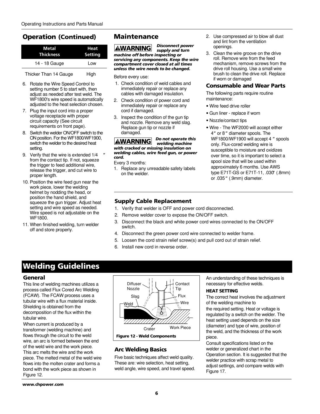
When current is produced by a transformer (welding machine) and flows through the circuit to the weld wire, an arc is formed between the end of the weld wire and the work piece. This arc melts the wire and the work piece. The melted metal of the weld wire flows into the molten crater and forms a bond with the work piece as shown in Figure 12.

Diffuser


Contact

Nozzle


Tip

Slag


Flux

Weld


Wire


Crater

Work Piece


Figure 12 - Weld Components

Arc Welding Basics

Five basic techniques affect weld quality. These are: wire selection, heat setting, weld angle, wire speed, and travel speed.

An understanding of these techniques is necessary for effective welds.

HEAT SETTING

The correct heat involves the adjustment of the welding machine to

the required setting. Heat or voltage is regulated by a switch on the welder. The heat setting used depends on the size (diameter) and type of wire, position of the weld, and the thickness of the work piece.

Consult specifications listed on the welder or generalized chart in the Operation section. It is suggested that the welder practice with scrap metal to adjust settings, and compare welds with Figure 17.

www.chpower.com

6

Page 6
Image 6
Campbell Hausfeld WF1900, WF1800, WF2000 operating instructions Welding Guidelines, Maintenance, Operation

WF1800, WF1900, WF2000 specifications

The Campbell Hausfeld WF2000, WF1900, and WF1800 are exceptional models in the realm of air compressors, tailored for various applications ranging from home projects to professional tasks. Each model retains a unique set of features while sharing a commitment to performance and reliability, making them popular choices among DIY enthusiasts and seasoned professionals alike.

Starting with the WF2000, this model is a powerful air compressor designed to handle demanding tasks. Boasting a 2-horsepower motor, it delivers up to 7.0 CFM at 40 PSI, which ensures quick recovery times for various pneumatic tools. The WF2000 features a durable oil-lubricated design, contributing to a longer lifespan and reduced wear. Additionally, its low noise design operates at a quieter level, providing a more pleasant working environment. The 4-gallon capacity tank offers substantial air storage, making it efficient for extended use.

Next in line is the WF1900, which offers a balance of performance and portability. This model utilizes a direct drive, oil-free pump system that not only allows for easy maintenance but also offers the convenience of instant startup and less noise compared to oil-lubricated counterparts. The WF1900 is equipped with a 1.5-horsepower motor and delivers 5.4 CFM at 90 PSI, catering well to nailers, staplers, and other light to medium-duty tools. With a compact design and a weight of under 50 pounds, it emphasizes mobility, making it ideal for various job sites or home use.

Finally, the WF1800 rounds out the trio with a focus on user-friendly features. It delivers an impressive performance with a 1.8-horsepower motor, reaching 6.2 CFM at 40 PSI. Like the WF1900, it features an oil-free pump, ensuring minimal maintenance while enabling continuous operation. The 3-gallon tank supports a wide range of applications, from inflating tires to powering airbrushes. Notably, the WF1800 comes equipped with a convenient handle for easy transport, making it a versatile solution for both indoor and outdoor projects.

In summary, the Campbell Hausfeld WF2000, WF1900, and WF1800 each provide distinct advantages tailored to their intended users. From high-capacity performance to portability and user-friendly operation, these air compressors exemplify the qualities of reliability and efficiency, making them indispensable tools in any workshop. The commitment to innovation and robust design further cements Campbell Hausfeld's reputation as a leader in the air compressor market, ensuring their products meet the needs of all users.