WG4000
Operation (Continued)
10.Position wire feed gun near work piece, and then lower the welding helmet by nodding the head or positioning hand shield. Then squeeze gun trigger. Adjust heat setting and wire speed as needed.
11.When finished welding, turn welder off and store properly.
Maintenance
Disconnect power supply and turn
welder off before inspecting or servicing any components. Keep the wire compartment cover closed at all times unless the wire needs replacement.
Before every use:
1.Check condition of weld cables and immediately repair or replace any cables with damaged insulation.
2.Check condition of power cord and immediately repair or replace any cord if damaged.
3.Inspect condition of gun tip and nozzle. Remove any weld slag. Replace gun tip or nozzle if damaged.
Do not operate this
! WARNING welding machine
with cracked or missing insulation on welding cables, wire feed gun, or power cord.
Every 3 months:
1.Replace any unreadable safety labels on the welder.
2.Use compressed air to blow all dust and lint from the ventilation openings.
3.Clean wire groove on drive roll. Remove wire from feed mechanism and remove screws from drive roll housing. Use a small wire brush to clean drive roll. Replace if worn or damaged.
CONSUMER AND WEAR PARTS
The following parts require routine maintenance:
•Wire feed drive roller
•Gun liner - replace if worn
•Nozzle/contact tips
•Wire - this welder will accept either
4” or 8” diameter spools. Welding wire is susceptible to moisture and oxidizes over time, so it is important to select a spool size that will be used within approximately 6 months. For mild steel welding, AWS ER70S6 solid wire or AWS
•Contact tips - use Campbell Hausfeld, Tweco®, and other compatible tips.
•Nozzle - use Tweco® style or compatible nozzle. Use Campbell Hausfeld nozzle model WT5021 found at place of purchase of welder, or use Tweco® style nozzle (or compatible nozzle) found at local welding supply store.
Changing Wire Sizes
DRIVE ROLLER
There are two grooves in the Drive Roller. The small groove is for .030"-
.035" (.8
CONTACT TIP
Make sure the contact tip size matches the wire size. If the tip is too small, there will be too much drag on the wire. If the tip is too large, arcing will occur inside the tip. This will burn the tip or cause carbon deposits inside the tip that insulate the tip from the wire.
Call (800)
for replacement parts.
Welding Guidelines
General |
| |
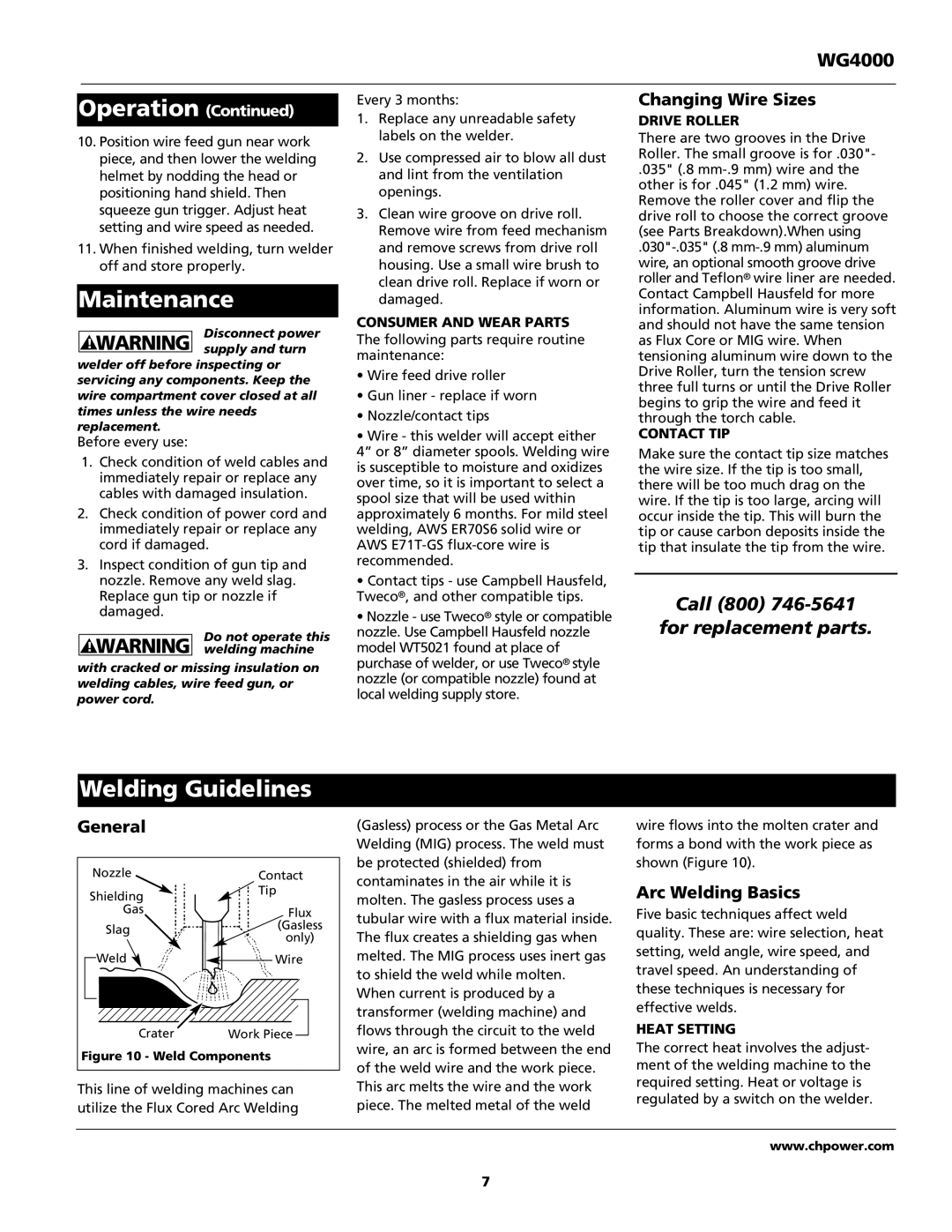
Nozzle | Contact | |
Shielding | Tip | |
| ||
Gas | Flux | |
Slag | (Gasless | |
only) | ||
| ||
Weld | Wire | |
Crater | Work Piece | |
Figure 10 - Weld Components | ||
This line of welding machines can utilize the Flux Cored Arc Welding
(Gasless) process or the Gas Metal Arc Welding (MIG) process. The weld must be protected (shielded) from contaminates in the air while it is molten. The gasless process uses a tubular wire with a flux material inside. The flux creates a shielding gas when melted. The MIG process uses inert gas to shield the weld while molten.
When current is produced by a transformer (welding machine) and flows through the circuit to the weld wire, an arc is formed between the end of the weld wire and the work piece. This arc melts the wire and the work piece. The melted metal of the weld
wire flows into the molten crater and forms a bond with the work piece as shown (Figure 10).
Arc Welding Basics
Five basic techniques affect weld quality. These are: wire selection, heat setting, weld angle, wire speed, and travel speed. An understanding of these techniques is necessary for effective welds.
HEAT SETTING
The correct heat involves the adjust- ment of the welding machine to the required setting. Heat or voltage is regulated by a switch on the welder.
www.chpower.com
7