Wire Feed Arc Welder |
|
|
|
| ||
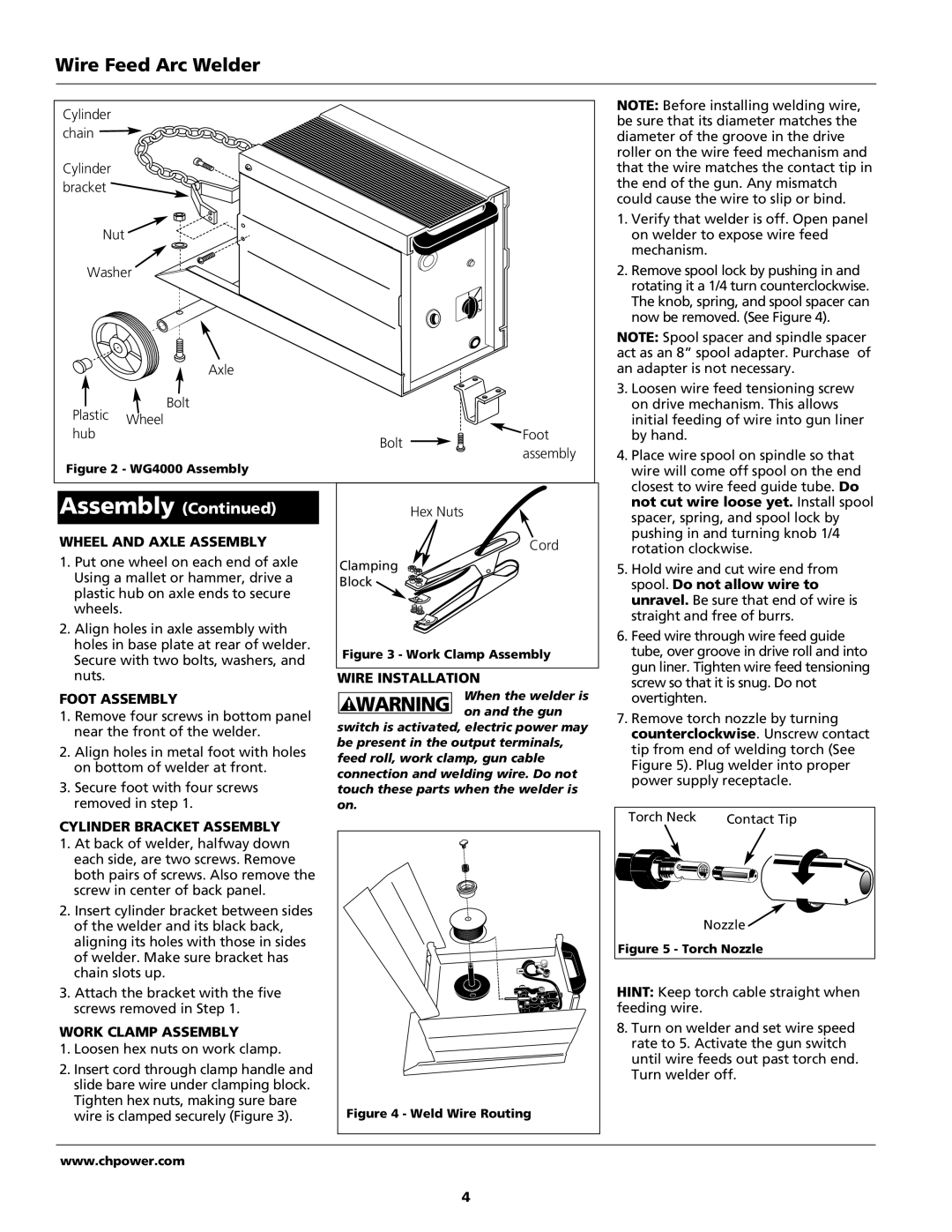
Cylinder |
|
|
| NOTE: Before installing welding wire, | ||
|
|
| be sure that its diameter matches the | |||
chain |
|
|
| |||
|
|
| diameter of the groove in the drive | |||
|
|
|
| roller on the wire feed mechanism and | ||
Cylinder |
|
|
| that the wire matches the contact tip in | ||
bracket |
|
|
| the end of the gun. Any mismatch | ||
|
|
| could cause the wire to slip or bind. | |||
|
|
|
| |||
|
|
|
| 1. Verify that welder is off. Open panel | ||
Nut |
|
|
| on welder to expose wire feed | ||
|
|
|
| mechanism. |
| |
Washer |
|
| 2. Remove spool lock by pushing in and | |||
|
|
|
| rotating it a 1/4 turn counterclockwise. | ||
|
|
|
| The knob, spring, and spool spacer can | ||
|
|
|
| now be removed. (See Figure 4). | ||
|
|
|
| NOTE: Spool spacer and spindle spacer | ||
|
|
|
| act as an 8” spool adapter. Purchase of | ||
| Axle |
|
| an adapter is not necessary. | ||
| Bolt |
|
| 3. Loosen wire feed tensioning screw | ||
Plastic |
|
| on drive mechanism. This allows | |||
Wheel |
|
| initial feeding of wire into gun liner | |||
hub |
| Foot | ||||
| Bolt | by hand. |
| |||
|
| assembly | 4. Place wire spool on spindle so that | |||
Figure 2 - WG4000 Assembly |
| |||||
|
| wire will come off spool on the end | ||||
Assembly (Continued) |
|
| closest to wire feed guide tube. Do | |||
Hex Nuts | not cut wire loose yet. Install spool | |||||
spacer, spring, and spool lock by | ||||||
|
|
|
| |||
WHEEL AND AXLE ASSEMBLY |
| Cord | pushing in and turning knob 1/4 | |||
| rotation clockwise. | |||||
1. Put one wheel on each end of axle | Clamping |
| 5. Hold wire and cut wire end from | |||
Using a mallet or hammer, drive a |
| |||||
Block |
| spool. Do not allow wire to | ||||
plastic hub on axle ends to secure |
| |||||
|
| unravel. Be sure that end of wire is | ||||
wheels. |
|
|
| |||
|
|
| straight and free of burrs. | |||
2. Align holes in axle assembly with |
|
| ||||
|
| 6. Feed wire through wire feed guide | ||||
holes in base plate at rear of welder. |
|
| ||||
Figure 3 - Work Clamp Assembly | tube, over groove in drive roll and into | |||||
Secure with two bolts, washers, and | ||||||
|
| gun liner. Tighten wire feed tensioning | ||||
nuts. |
| WIRE INSTALLATION | ||||
| screw so that it is snug. Do not | |||||
|
|
| When the welder is | |||
FOOT ASSEMBLY | ! WARNING | overtighten. |
| |||
1. Remove four screws in bottom panel | on and the gun | 7. Remove torch nozzle by turning | ||||
switch is activated, electric power may | ||||||
near the front of the welder. | counterclockwise. Unscrew contact | |||||
be present in the output terminals, | ||||||
2. Align holes in metal foot with holes | tip from end of welding torch (See | |||||
feed roll, work clamp, gun cable | ||||||
on bottom of welder at front. | Figure 5). Plug welder into proper | |||||
connection and welding wire. Do not | ||||||
3. Secure foot with four screws | power supply receptacle. | |||||
touch these parts when the welder is | ||||||
|
| |||||
removed in step 1. | on. |
| Torch Neck | Contact Tip | ||
CYLINDER BRACKET ASSEMBLY |
|
| ||||
|
|
|
| |||
1. At back of welder, halfway down |
|
|
|
| ||
each side, are two screws. Remove |
|
|
|
| ||
both pairs of screws. Also remove the |
|
|
|
| ||
screw in center of back panel. |
|
|
|
| ||
2. Insert cylinder bracket between sides |
|
| Nozzle | |||
of the welder and its black back, |
|
| ||||
aligning its holes with those in sides |
|
| Figure 5 - Torch Nozzle | |||
of welder. Make sure bracket has |
|
| ||||
|
|
|
| |||
chain slots up. |
|
|
|
| ||
3. Attach the bracket with the five |
|
| HINT: Keep torch cable straight when | |||
screws removed in Step 1. |
|
| feeding wire. |
| ||
WORK CLAMP ASSEMBLY |
|
| 8. Turn on welder and set wire speed | |||
1. Loosen hex nuts on work clamp. |
|
| rate to 5. Activate the gun switch | |||
|
| until wire feeds out past torch end. | ||||
2. Insert cord through clamp handle and |
|
| ||||
|
| Turn welder off. | ||||
slide bare wire under clamping block. |
|
| ||||
|
|
|
| |||
Tighten hex nuts, making sure bare | Figure 4 - Weld Wire Routing |
|
| |||
wire is clamped securely (Figure 3). |
|
| ||||
www.chpower.com |
|
|
|
| ||
|
|
| 4 |
|
| |