Installation
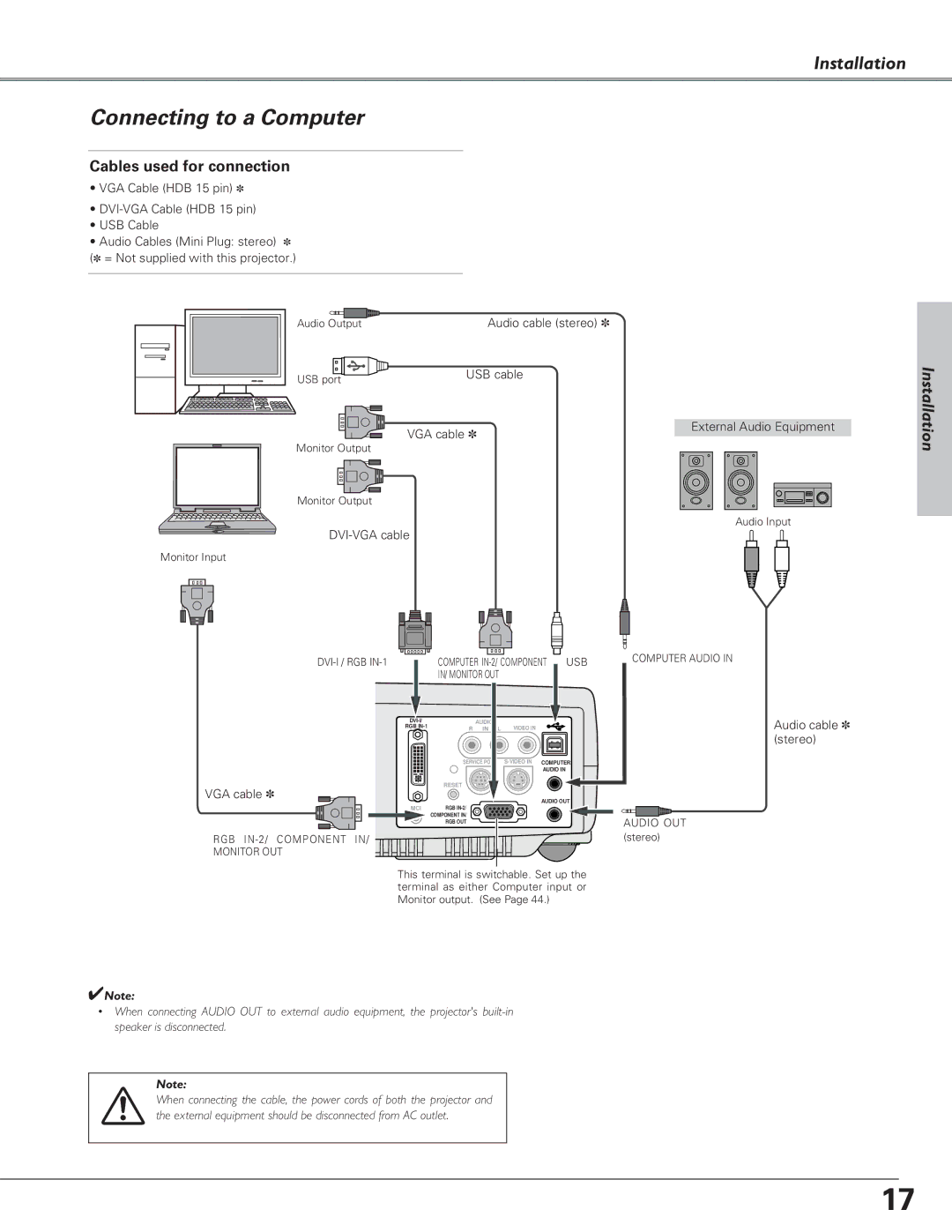
Connecting to a Computer
Cables used for connection
•VGA Cable (HDB 15 pin) ✽
•
•USB Cable
•Audio Cables (Mini Plug: stereo) ✽ (✽ = Not supplied with this projector.)
Audio Output
USB port
Audio cable (stereo) ✽
USB cable
Installation
VGA cable ✽
Monitor Output |
Monitor Output |
Monitor Input
External Audio Equipment
Audio Input
COMPUTER | USB | |||||
| IN/ MONITOR OUT |
|
|
| ||
| AUDIO |
|
|
|
| |
RGB | R | IN | L | VIDEO IN |
|
|
| SERVICE PORT |
| COMPUTER | |||
|
|
|
|
| AUDIO IN |
|
VGA cable ✽ | RESET |
|
|
|
|
|
|
|
|
| AUDIO OUT | ||
|
|
|
|
| ||
MCI | RGB |
|
|
|
|
|
| COMPONENT IN/ |
|
|
|
|
|
| RGB OUT |
|
|
|
|
|
RGB IN-2/ COMPONENT IN/
MONITOR OUT
This terminal is switchable. Set up the terminal as either Computer input or Monitor output. (See Page 44.)
✔Note:
•When connecting AUDIO OUT to external audio equipment, the projector's
Note:
When connecting the cable, the power cords of both the projector and the external equipment should be disconnected from AC outlet.
COMPUTER AUDIO IN
AUDIO OUT (stereo)
Audio cable ✽ (stereo)
17