Part Names and Functions
Rear Terminal
q | w | e |
| r | t | y |
DVI - I / |
| AUDIO |
|
|
|
|
RGB | R | IN | L | VIDEO IN |
|
|
|
|
| ||||
✽ | SERVICE PORT |
| COMPUTER |
| ||
|
|
|
|
| AUDIO IN |
|
| RESET |
|
|
|
|
|
 AUDIO OUT
MCI | RGB |
| COMPONENT IN / |
| RGB OUT |
Do not press this button. This button is used for optional |
| o |
| i |
| u |
accessories. |
|
|
|
|
|
|
|
|
|
|
| ||
|
|
|
|
|
|
|
Part Names and Functions
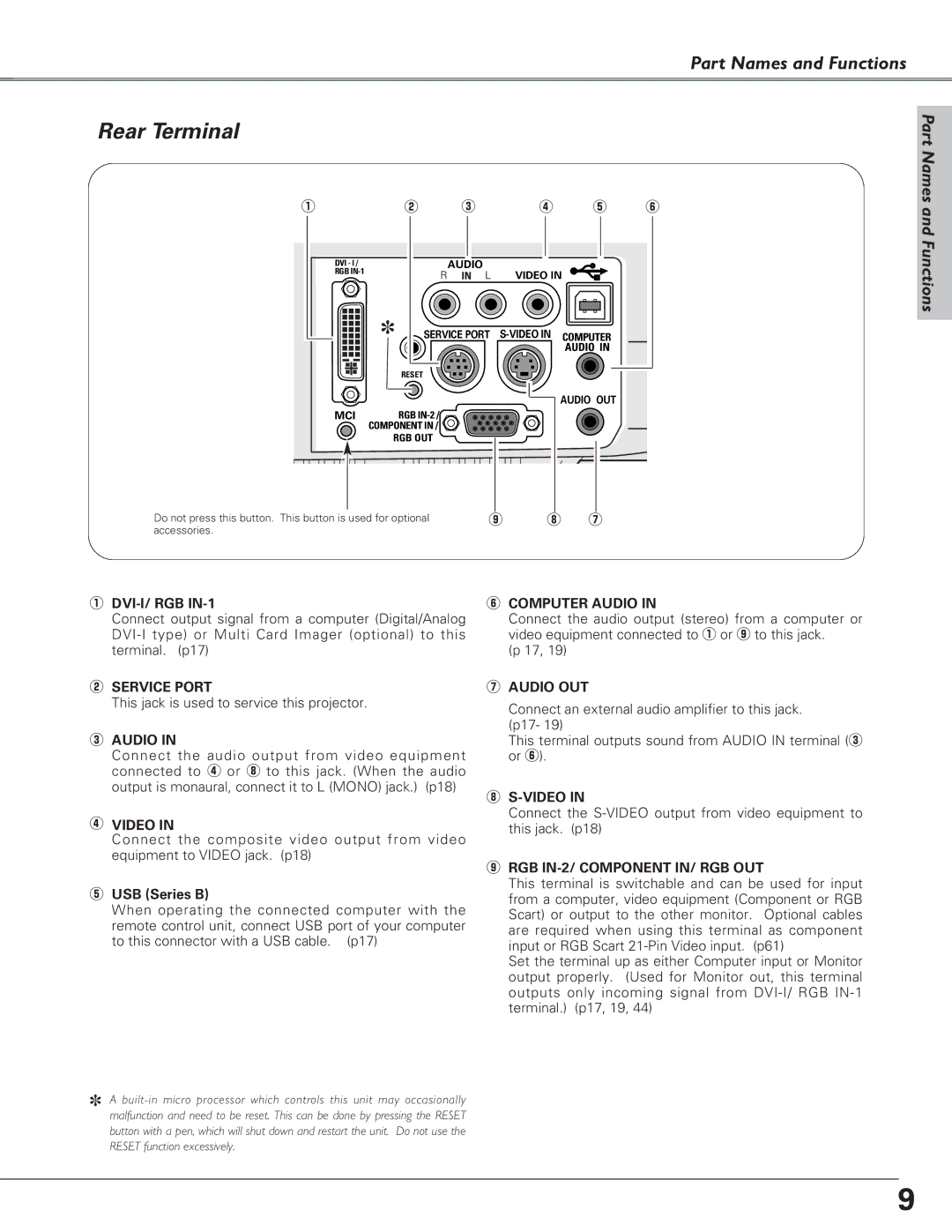
qDVI-I/ RGB IN-1
Connect output signal from a computer (Digital/Analog
wSERVICE PORT
This jack is used to service this projector.
eAUDIO IN
Connect the audio output from video equipment connected to r or i to this jack. (When the audio output is monaural, connect it to L (MONO) jack.) (p18)
rVIDEO IN
Connect the composite video output from video equipment to VIDEO jack. (p18)
tUSB (Series B)
When operating the connected computer with the remote control unit, connect USB port of your computer to this connector with a USB cable. (p17)
✽A
button with a pen, which will shut down and restart the unit. Do not use the RESET function excessively.
yCOMPUTER AUDIO IN
Connect the audio output (stereo) from a computer or video equipment connected to q or o to this jack.
(p 17, 19)
uAUDIO OUT
Connect an external audio amplifier to this jack.
(p17- 19)
This terminal outputs sound from AUDIO IN terminal (e or y).
i
Connect the
oRGB IN-2/ COMPONENT IN/ RGB OUT
This terminal is switchable and can be used for input from a computer, video equipment (Component or RGB Scart) or output to the other monitor. Optional cables are required when using this terminal as component input or RGB Scart
Set the terminal up as either Computer input or Monitor output properly. (Used for Monitor out, this terminal outputs only incoming signal from
9