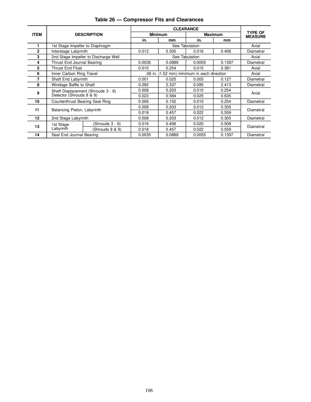
17EX specifications
The Carrier 17EX is recognized as an innovative air conditioning solution that combines efficiency with advanced technology. This model is designed to meet the increasing demands of residential and commercial cooling needs while maintaining environmental consciousness.One of the standout features of the Carrier 17EX is its impressive Seasonal Energy Efficiency Ratio (SEER) rating. With a SEER rating that often exceeds 17, this unit ensures optimized energy consumption, significantly lowering operational costs for users. The incorporation of advanced compressor technology allows the system to adjust its cooling output based on the specific needs of the environment, thus providing both comfort and energy savings.
The Carrier 17EX utilizes a variable-speed inverter-driven compressor that enhances its performance and adaptability. This technology allows the air conditioning unit to operate at different speeds, intelligently adjusting to changing load conditions. As a result, the system runs more efficiently and quietly, providing a more consistent comfort level without the abrupt temperature swings associated with traditional units.
In addition to efficiency, the Carrier 17EX also prioritizes reliability and durability. The unit comes with a robust cabinet that protects the components from weather elements, ensuring longevity and consistent performance. The innovative design integrates a corrosion-resistant finish and robust insulation, which further enhances the unit's resilience in various environmental conditions.
For users concerned about indoor air quality, the Carrier 17EX includes advanced filtration systems designed to capture allergens and airborne particles. This feature is particularly beneficial for individuals with respiratory issues, ensuring that the air circulated within the space is clean and healthy.
Moreover, the Carrier 17EX is equipped with smart technology capabilities, allowing users to control their systems remotely through smartphones or other smart devices. This connectivity not only provides convenience but also empowers homeowners to optimize their energy use by adjusting settings on the fly, ensuring efficient operation even when they are away from home.
Overall, the Carrier 17EX stands out in the marketplace for its exceptional energy efficiency, advanced technology, and commitment to providing reliable and effective cooling solutions. Its combination of modern features makes it a preferred choice for those looking to enhance comfort while being mindful of energy consumption and environmental impact.
