5.After the last digit is changed, the LID goes to the BUS # parameter. Press the EXIT softkey to leave the

screen, record your password change, and return to the SERVICE menu.

BE SURE TO REMEMBER YOUR PASSWORD. Retain a copy of the password for future reference. If you forget your password, you will not be able to access the SERVICE menu unless you install and download a new PSIO module.

INPUT TIME AND DATE Ð Access the Time and Date table on the SERVICE menu. Input the present time of day, date, and day of the week. HOLIDAY TODAY should only be con®gured to YES if the present day is a holiday.

CHANGE THE LID CONFIGURATION IF NECESSARY

ÐFrom the LID CONFIGURATION screen, the LID CCN address, units (English or SI), and password can be changed. If there is more than one chiller at the jobsite, change the LID address on each chiller so that each chiller has its own address. Note and record the new address. Change the screen to SI units as required, and change the password if desired.

To Change the LID Display From English to Metric Units

ÐBy default, the LID displays information in English units. To change to metric units:

1.Press the MENU and SERVICE softkeys. Enter your pass- word and highlight LID CONFIGURATION. Press the SELECT softkey.

2.Use the ENTER softkey to scroll to US IMP/METRIC.

3.Press the softkeys that correspond to the units you want displayed on the LID (e.g., US or METRIC ).

MODIFY CONTROLLER IDENTIFICATION IF NECES- SARY Ð The PSIO module address can be changed from the CONTROLLER IDENTIFICATION screen. If there is more than one chiller at the site, change the controller ad- dress for each chiller. Write the new address on the PSIO module for future reference.

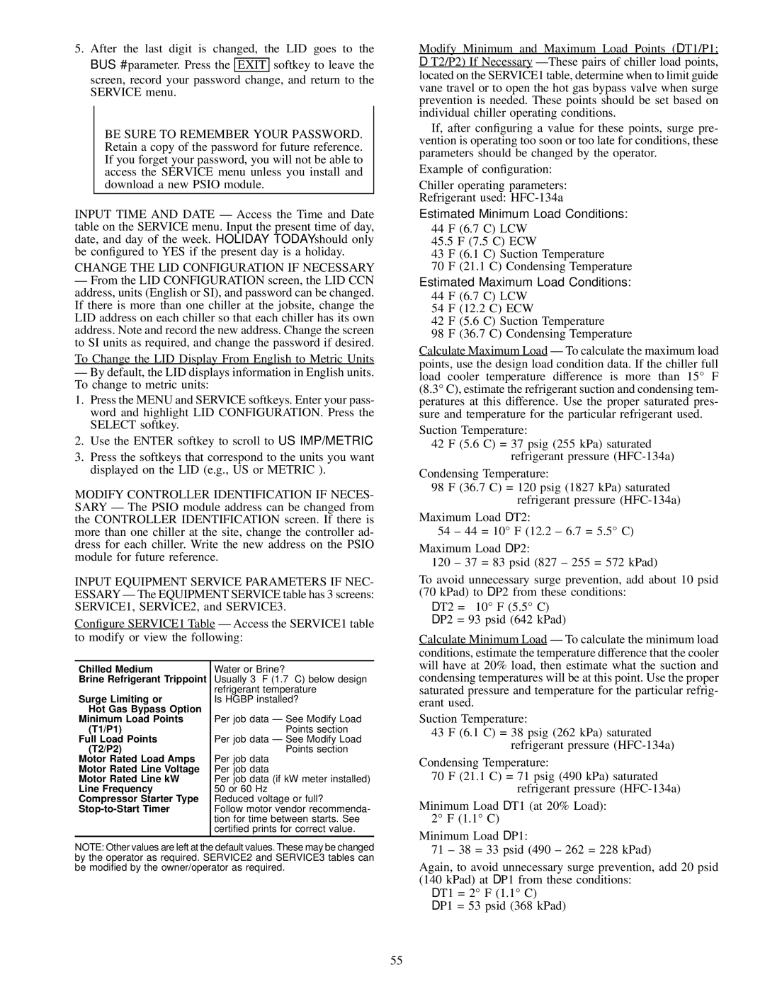
INPUT EQUIPMENT SERVICE PARAMETERS IF NEC- ESSARY Ð The EQUIPMENT SERVICE table has 3 screens: SERVICE1, SERVICE2, and SERVICE3.

Con®gure SERVICE1 Table Ð Access the SERVICE1 table to modify or view the following:

Modify Minimum and Maximum Load Points (DT1/P1;

DT2/P2) If Necessary ÐThese pairs of chiller load points, located on the SERVICE1 table, determine when to limit guide vane travel or to open the hot gas bypass valve when surge prevention is needed. These points should be set based on individual chiller operating conditions.

If, after con®guring a value for these points, surge pre- vention is operating too soon or too late for conditions, these parameters should be changed by the operator.

Example of con®guration:

Chiller operating parameters: Refrigerant used: HFC-134a

Estimated Minimum Load Conditions:

44 F (6.7 C) LCW

45.5 F (7.5 C) ECW

43 F (6.1 C) Suction Temperature

70 F (21.1 C) Condensing Temperature Estimated Maximum Load Conditions:

44 F (6.7 C) LCW

54 F (12.2 C) ECW

42 F (5.6 C) Suction Temperature

98 F (36.7 C) Condensing Temperature

Calculate Maximum Load Ð To calculate the maximum load points, use the design load condition data. If the chiller full load cooler temperature difference is more than 15° F (8.3° C), estimate the refrigerant suction and condensing tem- peratures at this difference. Use the proper saturated pres- sure and temperature for the particular refrigerant used.

Suction Temperature:

42 F (5.6 C) = 37 psig (255 kPa) saturated refrigerant pressure (HFC-134a)

Condensing Temperature:

98 F (36.7 C) = 120 psig (1827 kPa) saturated refrigerant pressure (HFC-134a)

Maximum Load DT2:

54 ± 44 = 10° F (12.2 ± 6.7 = 5.5° C)

Maximum Load DP2:

120 ± 37 = 83 psid (827 ± 255 = 572 kPad)

To avoid unnecessary surge prevention, add about 10 psid

(70 kPad) to DP2 from these conditions:

DT2 = 10° F (5.5° C)

DP2 = 93 psid (642 kPad)

Calculate Minimum Load Ð To calculate the minimum load conditions, estimate the temperature difference that the cooler will have at 20% load, then estimate what the suction and

Chilled Medium

Brine Refrigerant Trippoint

Surge Limiting or

Hot Gas Bypass Option Minimum Load Points

(T1/P1)

Full Load Points (T2/P2)

Motor Rated Load Amps Motor Rated Line Voltage Motor Rated Line kW Line Frequency Compressor Starter Type Stop-to-Start Timer

Water or Brine?

Usually 3° F (1.7° C) below design refrigerant temperature

Is HGBP installed?

Per job data Ð See Modify Load Points section

Per job data Ð See Modify Load Points section

Per job data Per job data

Per job data (if kW meter installed) 50 or 60 Hz

Reduced voltage or full?

Follow motor vendor recommenda- tion for time between starts. See certi®ed prints for correct value.

condensing temperatures will be at this point. Use the proper saturated pressure and temperature for the particular refrig- erant used.

Suction Temperature:

43 F (6.1 C) = 38 psig (262 kPa) saturated refrigerant pressure (HFC-134a)

Condensing Temperature:

70 F (21.1 C) = 71 psig (490 kPa) saturated

refrigerant pressure (HFC-134a)

Minimum Load DT1 (at 20% Load):

2° F (1.1° C)

Minimum Load DP1:

NOTE: Other values are left at the default values. These may be changed by the operator as required. SERVICE2 and SERVICE3 tables can be modi®ed by the owner/operator as required.

71 ± 38 = 33 psid (490 ± 262 = 228 kPad)

Again, to avoid unnecessary surge prevention, add 20 psid

(140 kPad) at DP1 from these conditions: DT1 = 2° F (1.1° C)

DP1 = 53 psid (368 kPad)

55

Page 55
Image 55
Carrier 17EX specifications Change the LID Configuration if Necessary, Surge Limiting or, T1/P1 Full Load Points T2/P2

17EX specifications

The Carrier 17EX is recognized as an innovative air conditioning solution that combines efficiency with advanced technology. This model is designed to meet the increasing demands of residential and commercial cooling needs while maintaining environmental consciousness.

One of the standout features of the Carrier 17EX is its impressive Seasonal Energy Efficiency Ratio (SEER) rating. With a SEER rating that often exceeds 17, this unit ensures optimized energy consumption, significantly lowering operational costs for users. The incorporation of advanced compressor technology allows the system to adjust its cooling output based on the specific needs of the environment, thus providing both comfort and energy savings.

The Carrier 17EX utilizes a variable-speed inverter-driven compressor that enhances its performance and adaptability. This technology allows the air conditioning unit to operate at different speeds, intelligently adjusting to changing load conditions. As a result, the system runs more efficiently and quietly, providing a more consistent comfort level without the abrupt temperature swings associated with traditional units.

In addition to efficiency, the Carrier 17EX also prioritizes reliability and durability. The unit comes with a robust cabinet that protects the components from weather elements, ensuring longevity and consistent performance. The innovative design integrates a corrosion-resistant finish and robust insulation, which further enhances the unit's resilience in various environmental conditions.

For users concerned about indoor air quality, the Carrier 17EX includes advanced filtration systems designed to capture allergens and airborne particles. This feature is particularly beneficial for individuals with respiratory issues, ensuring that the air circulated within the space is clean and healthy.

Moreover, the Carrier 17EX is equipped with smart technology capabilities, allowing users to control their systems remotely through smartphones or other smart devices. This connectivity not only provides convenience but also empowers homeowners to optimize their energy use by adjusting settings on the fly, ensuring efficient operation even when they are away from home.

Overall, the Carrier 17EX stands out in the marketplace for its exceptional energy efficiency, advanced technology, and commitment to providing reliable and effective cooling solutions. Its combination of modern features makes it a preferred choice for those looking to enhance comfort while being mindful of energy consumption and environmental impact.