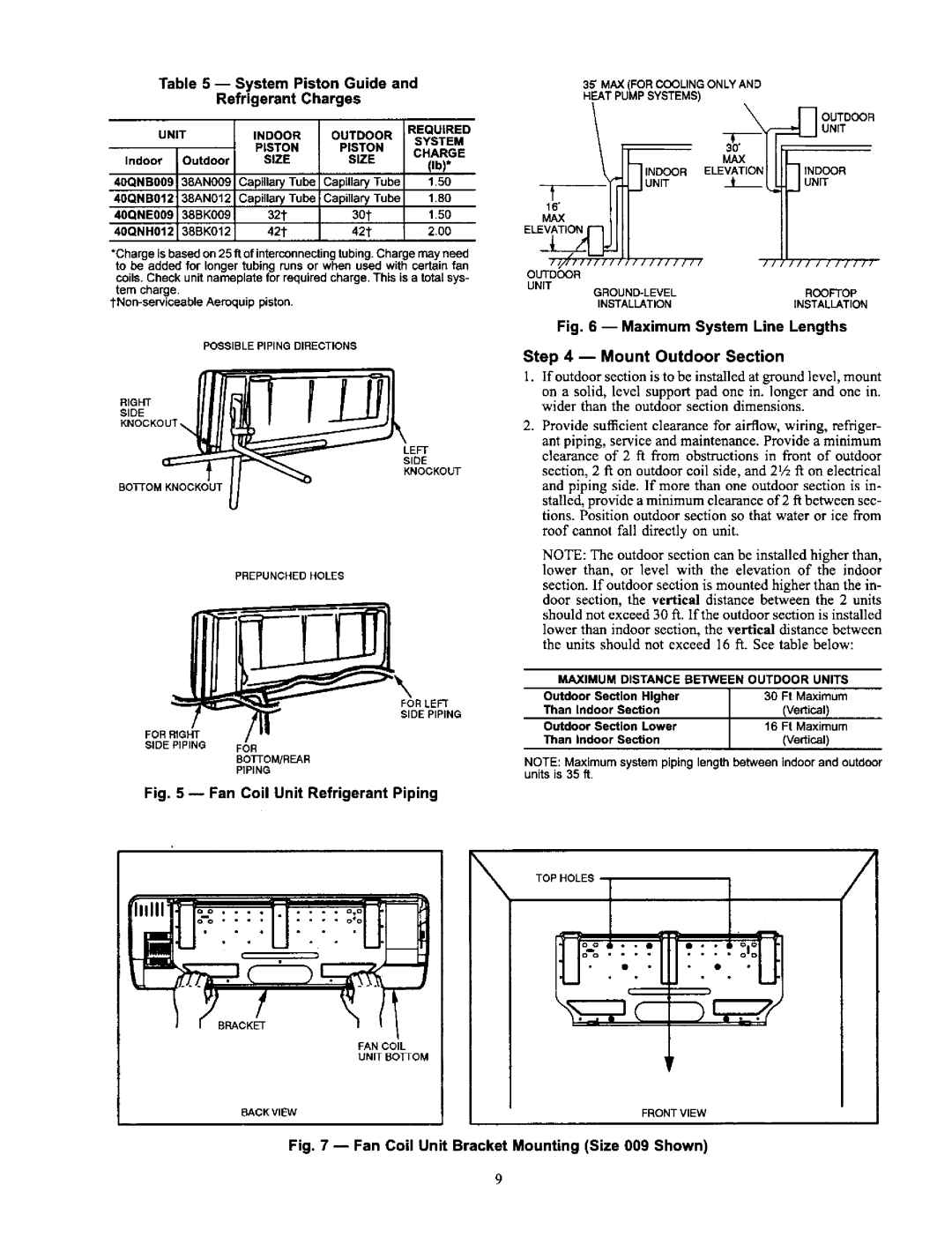
38AN,BK specifications
The Carrier 38AN,BK is a distinguished model in the world of air conditioning, known for its advanced features, innovative technologies, and exceptional performance. This air conditioning unit is particularly favored for residential and small commercial applications, offering a perfect blend of efficiency, reliability, and comfort.One of the main features of the Carrier 38AN,BK is its high energy efficiency, which is crucial in today’s eco-conscious environment. With a Seasonal Energy Efficiency Ratio (SEER) rating that often exceeds industry standards, this unit ensures minimal energy consumption while providing powerful cooling capabilities. This not only contributes to lower utility bills but also reduces the overall carbon footprint.
The Carrier 38AN,BK employs advanced cooling technologies that make it a standout choice. One notable feature is its use of a scroll compressor, which operates with fewer moving parts than traditional models, resulting in reduced noise levels and enhanced durability. This compressor design also ensures a smoother operation, translating to consistent temperature control and a more comfortable indoor environment.
Another innovative technology incorporated in the Carrier 38AN,BK is the use of smart controls, allowing users to easily adjust settings and monitor performance through compatible smart devices. This feature adds convenience and flexibility, enabling homeowners to manage their home climate efficiently, even when they are away.
In terms of construction, the Carrier 38AN,BK’s robust design includes a galvanized steel cabinet that is resistant to corrosion and designed to withstand adverse weather conditions. This ensures longevity and reliable performance throughout the year. Additionally, the unit features advanced filtration systems that help improve indoor air quality by reducing allergens and pollutants, further enhancing user comfort.
Furthermore, the Carrier 38AN,BK is designed to operate quietly, making it an ideal choice for bedrooms and other quiet spaces. Its noise reduction features, combined with its energy-saving capabilities, position it as an attractive choice for a wide range of applications.
In summary, the Carrier 38AN,BK air conditioning unit excels in efficiency, advanced technologies, and user-friendly features. Its reliable design and quiet operation make it a top choice for anyone seeking effective and environmentally responsible cooling solutions. As both technology-savvy and eco-friendly, it meets the demands of modern homeowners while delivering exceptional comfort year-round.

