START-UP
Complete the following checks and the Start-Up Check- list on pages CL-1 and CL-2 before system start-up.
1. Check condensate drainage system. Refer to Fig. 4 and 10. Add water to check the drainage flow. If water does not flow steadily, check the pipe slope or see if there are any restrictions.
2.Make sure all wiring connections are correct and tight.
3.Be sure all barriers, covers, and panels are in place.
4.Ensure that the filters have been installed and that the air discharge louvers are correctly positioned.
Never operate unit without a filter. Damage to the unit could result.
5.Fully backseat (open) the liquid and vapor tube service valves.
6.Unit is shipped with valve stems frontseated and caps fac- tory installed. Replace stem caps after system is opened to refrigerant flow (backseated). Replace caps finger fight.
7.With the remote controller, turn on the unit and operate in each mode (as applicable) for 15 minutes to test for proper operation. Do not operate in Cooling mode if out- door temperature is below 55 F, unless unit is equipped with low ambient control. Do not operalg in Heating mode
(heat pump systems only) if the outdoor temperature is above 75 F.
8.Test forproper refrigerant charge using the superheat method.
9.Explain basic system operation to the owner.
40QN Control System --The 40QN unit is equipped
with a microprocessor control which operates the system.
This control is located in the control box of the fan coil unit, with thermistors located in the fan coil inlet and on the in-
door coil. The 40QNE/H heat pump fan coil units also have thermistors located on the outdoor coil and in the outdoor air
inlet. These thermistors monitor system operation and con- trol the operating mode. To change settings or modes of op-
eration, use the factory-supplied infrared wireless remote controller. This controller allows the fan coil unit to be op- elated from within the same room without any wire connec- tions to the unit.
Wireless Remote Controllers --A wireless remote
controller is supplied for system operation of all high
wall units. Each battery-operated wireless (infrared) remote controller may be used to control more than one unit. The wireless remote controller has a maximum range of 20 feet. The fan coil unit is equipped with an emergency switch which allows operation if the remote controller malfunc- tions or is misplaced. Because the controller uses infrared
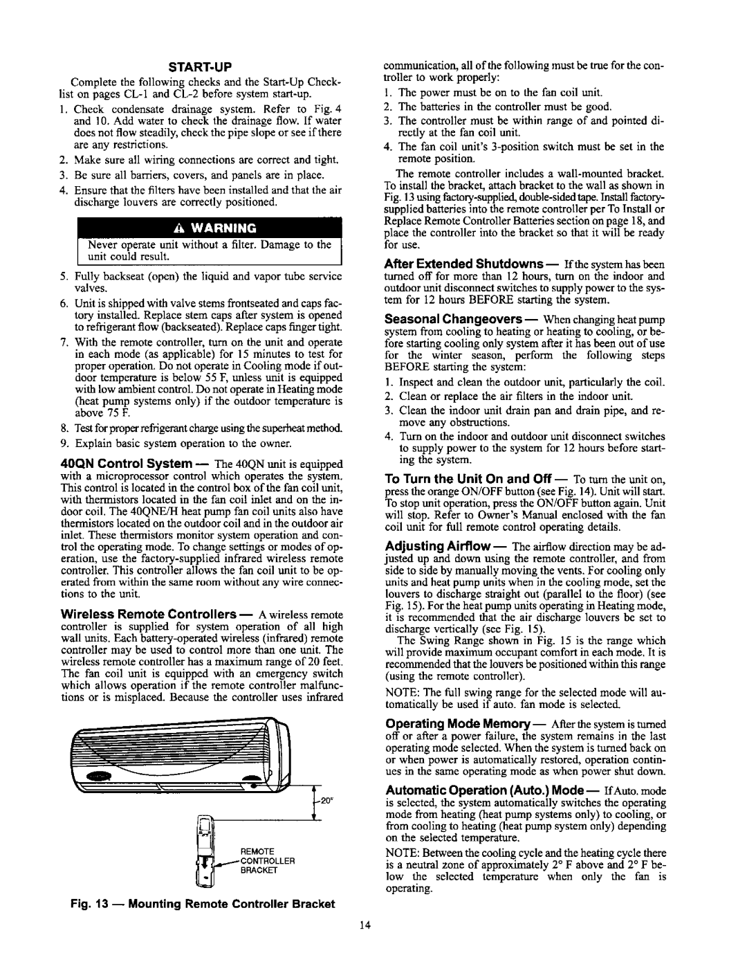
REMOTE
BRACKET
Fig. 13 --Mounting Remote Controller Bracket
communication, all of the following must be true for the con- troller to work properly:
1.The power must be on to the fan coil unit.
2.The batteries in the controller must be good.
3.The controller must be within range of and pointed di- rectly at the fan coil unit.
4.The fan coil unit's 3-position switch must be set in the remote position.
The remote controller includes a wall-mounted bracket. To install the bracket, attach bracket to the wall as shown in Fig. 13 u.fmg factory-supplied, double-sided tape. Install factory- supplied batteries into the remote controller per To Install or Replace Remote Controller Batteries section on page 18, and place the controller into the bracket so that it will be ready for use.
After Extended Shutdowns-- If the system has been turned off for more than 12 hours, turn on the indoor and outdoor unit disconnect switches to supply power to the sys- tem for 12 hours BEFORE starting the system.
Seasonal Changeovers--When changingheat pump system from cooling to heating or heating to cooling, or be-
fore starting cooling only system after it has been out of use
for the winter season, perform the following steps BEFORE starting the system:
1.Inspect and clean the outdoor unit, particularly the coil.
2.Clean or replace the air filters in the indoor unit.
3.Clean the indoor unit drain pan and drain pipe, and re- move any obstructions.
4.Turn on the indoor and outdoor unit disconnect switches
to supply power to the system for 12 hours before start- ing the system.
To Turn the Unit On and Off -- To turn the unit on, press the orange ON/OFF button (see Fig. 14). Unit will start. To stop unit operation, press the ON/OFF button again. Unit will stop. Refer to Owner's Manual enclosed with the fan coil unit for full remote control operating details.
Adjusting Airflow -- The airflow direction may be ad- justed up and down using the remote controller, and from side to side by manually moving the vents. For cooling only units and heat pump units when in the cooling mode, set the louvers to discharge straight out (parallel to the floor) (see Fig. 15). For the heat pump units operating in Heating mode,
it is recommended that the air discharge louvers be set to discharge vertically (see Fig. 15).
The Swing Range shown in Fig. 15 is the range which will provide maximum occupant comfort in each mode. It is recommended that the louvers be positioned within this range (using the remote controller).
NOTE: The full swing range for the selected mode will au- tomatically be used if auto. fan mode is selected.
Operating Mode Memory--After the system is turned off or after a power failure, the system remains in the last operating mode selected. When the system is turned back on or when power is automatically restored, operation contin- ues in the same operating mode as when power shut down.
Automatic Operation (Auto.) Mode--IfAuto. mode is selected, the system automatically switches the operating mode from heating (heat pump systems only) to cooling, or from cooling to heating (heat pump system only) depending on the selected tempemture.
NOTE: Between the cooling cycle and the heating cycle there is a neutral zone of approximately 2 ° F above and 2 ° F be-
low the selected temperature when only the fan is operating.