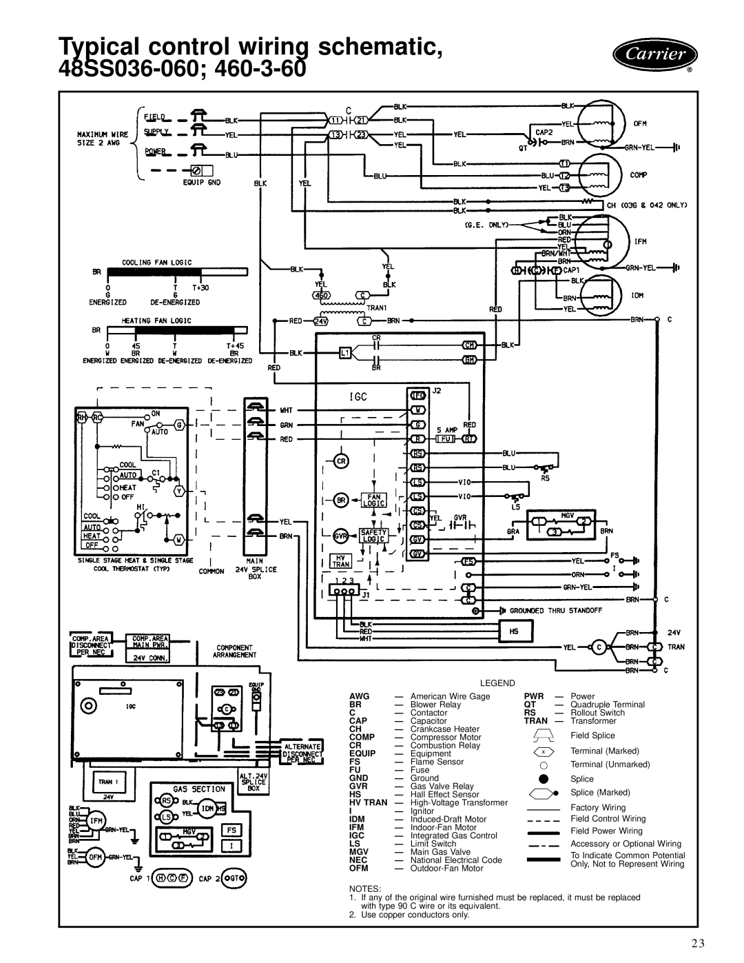
Typical control wiring schematic,
48SS036-060; 460-3-60
|
| LEGEND |
|
|
AWG | Ð American Wire Gage | PWR | Ð Power | |
BR | Ð Blower Relay | QT | Ð Quadruple Terminal | |
C | Ð Contactor | RS | Ð Rollout Switch | |
CAP | Ð | Capacitor | TRAN | Ð Transformer |
CH | Ð Crankcase Heater |
| Field Splice | |
COMP | Ð Compressor Motor |
| ||
CR | Ð Combustion Relay |
| Terminal (Marked) | |
EQUIP | Ð | Equipment |
| |
FS | Ð | Flame Sensor |
| Terminal (Unmarked) |
FU | Ð | Fuse |
| |
|
| |||
GND | Ð Ground |
| Splice | |
GVR | Ð Gas Valve Relay |
| Splice (Marked) | |
HS | Ð Hall Effect Sensor |
| ||
HV TRAN | Ð |
| Factory Wiring | |
I | Ð | Ignitor |
| |
IDM | Ð |
| Field Control Wiring | |
IFM | Ð |
| Field Power Wiring | |
IGC | Ð | Integrated Gas Control |
| |
|
| |||
LS | Ð | Limit Switch |
| Accessory or Optional Wiring |
MGV | Ð Main Gas Valve |
| To Indicate Common Potential | |
NEC | Ð | National Electrical Code |
| |
| Only, Not to Represent Wiring | |||
OFM | Ð |
| ||
|
| |||
NOTES:
1.If any of the original wire furnished must be replaced, it must be replaced with type 90 C wire or its equivalent.
2.Use copper conductors only.
23
