MECHANICAL COOLING LOCKOUT — Determine the
DRY BULB CHANGEOVER SET UP — Determine the dry bulb changeover set point from Table 5. The settings are A, B, C and D. Locate the ECON SP potentiometer and set the dry bulb changeover set point. See Fig. 16. When the OAT is above this set point, the damper is limited to minimum position setting.
If a potentiometer fails, its setting will default to the values in Table 6.
Table 4 — EconoMi$er Switchover Control Strategy
ECONOMI$ER SWITCHOVER |
| SENSORS REQUIRED |
| |
STRATEGY | Outdoor Air Temperature | Outdoor Air Enthalpy | Return Air Temperature | Return Air Enthalpy |
Dry Bulb | X |
|
|
|
|
|
|
|
|
Single Enthalpy |
| X |
|
|
|
|
|
|
|
Differential Temperature | X |
| X |
|
|
|
|
|
|
Differential Enthalpy* |
| X |
| X |
|
|
|
|
|
*Must be selected manually.
Table 5 — Changeover Set Points
SETTINGS | A | B | C | D | |
Dry Bulb (°F) | 73 | 69 | 66 | 63 | |
Single Enthalpy* (Btu/lb) | 27 | 25 | 24 | 22 | |
Differential Temperature* | 2 | 2 | 2 | 2 | |
(°F, Not Adjustable) | |||||
|
|
|
| ||
Differential Enthalpy* | 1 | 1 | 1 | 1 | |
(Btu/lb, Not Adjustable) | |||||
|
|
|
| ||
|
|
|
|
Table 6 — Default Potentiometer Settings
POTENTIOMETER | DEFAULT SETTING |
CO2 SP (PPM) | 1,000 |
MECH CLG LOCKOUT | 50 F |
ECON SP | D |
MIN POS (%) | 20 |
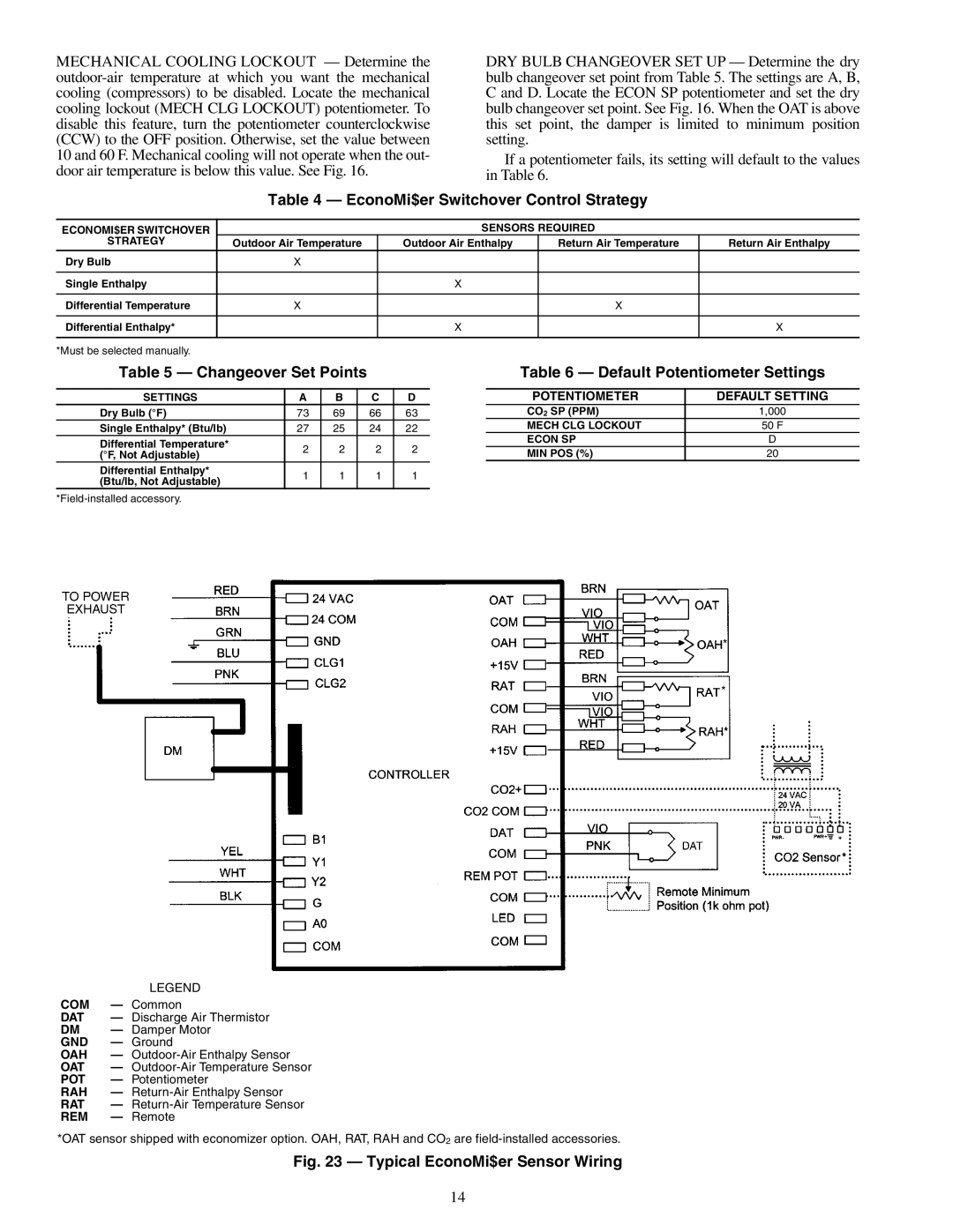
| LEGEND |
COM | — Common |
DAT | — Discharge Air Thermistor |
DM | — Damper Motor |
GND | — Ground |
OAH | — |
OAT | — |
POT | — Potentiometer |
RAH | — |
RAT | — |
REM | — Remote |
*OAT sensor shipped with economizer option. OAH, RAT, RAH and CO2 are
Fig. 23 — Typical EconoMi$er Sensor Wiring
14