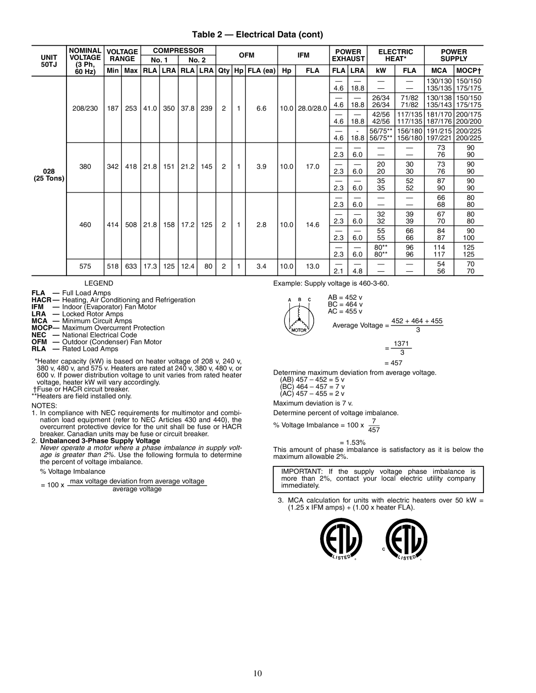
Table 2 — Electrical Data (cont)
UNIT | NOMINAL | VOLTAGE | COMPRESSOR |
| OFM |
|
| IFM | POWER | ELECTRIC | POWER | ||||||||
VOLTAGE | RANGE | No. 1 | No. 2 |
|
|
| EXHAUST | HEAT* | SUPPLY | ||||||||||
|
|
|
|
|
| ||||||||||||||
50TJ | (3 Ph, |
|
|
|
|
|
|
|
|
|
|
|
|
|
|
|
|
|
|
| 60 Hz) | Min | Max | RLA | LRA | RLA | LRA | Qty | Hp | FLA (ea) | Hp | FLA | FLA | LRA | kW | FLA | MCA | MOCP† | |
|
|
|
|
|
|
|
|
|
|
|
|
|
| — | — | — | — | 130/130 | 150/150 |
|
|
|
|
|
|
|
|
|
|
|
|
|
| 4.6 | 18.8 | — | — | 135/135 | 175/175 |
|
|
|
|
|
|
|
|
|
|
|
|
|
| — | — | 26/34 | 71/82 | 130/138 | 150/150 |
| 208/230 | 187 | 253 | 41.0 | 350 | 37.8 | 239 | 2 | 1 |
| 6.6 | 10.0 | 28.0/28.0 | 4.6 | 18.8 | 26/34 | 71/82 | 135/143 | 175/175 |
|
| — | — | 42/56 | 117/135 | 181/170 | 200/175 | ||||||||||||
|
|
|
|
|
|
|
|
|
|
|
|
|
| ||||||
|
|
|
|
|
|
|
|
|
|
|
|
|
| 4.6 | 18.8 | 42/56 | 117/135 | 187/176 | 200/200 |
|
|
|
|
|
|
|
|
|
|
|
|
|
| — | - | 56/75** | 156/180 | 191/215 | 200/225 |
|
|
|
|
|
|
|
|
|
|
|
|
|
| 4.6 | 18.8 | 56/75** | 156/180 | 197/221 | 200/225 |
|
|
|
|
|
|
|
|
|
|
|
|
|
| — | — | — | — | 73 | 90 |
|
|
|
|
|
|
|
|
|
|
|
|
|
| 2.3 | 6.0 | — | — | 76 | 90 |
028 | 380 | 342 | 418 | 21.8 | 151 | 21.2 | 145 | 2 | 1 |
| 3.9 | 10.0 | 17.0 | — | — | 20 | 30 | 73 | 90 |
| 2.3 | 6.0 | 20 | 30 | 76 | 90 | |||||||||||||
|
|
|
|
|
|
|
|
|
|
|
|
| |||||||
(25 Tons) |
|
|
|
|
|
|
|
|
|
|
|
|
| — | — | 35 | 52 | 87 | 90 |
|
|
|
|
|
|
|
|
|
|
|
|
|
| 2.3 | 6.0 | 35 | 52 | 90 | 90 |
|
|
|
|
|
|
|
|
|
|
|
|
|
| — | — | — | — | 66 | 80 |
|
|
|
|
|
|
|
|
|
|
|
|
|
| 2.3 | 6.0 | — | — | 68 | 80 |
|
|
|
|
|
|
|
|
|
|
|
|
|
| — | — | 32 | 39 | 67 | 80 |
| 460 | 414 | 508 | 21.8 | 158 | 17.2 | 125 | 2 | 1 |
| 2.8 | 10.0 | 14.6 | 2.3 | 6.0 | 32 | 39 | 70 | 80 |
|
| — | — | 55 | 66 | 84 | 90 | ||||||||||||
|
|
|
|
|
|
|
|
|
|
|
|
|
| ||||||
|
|
|
|
|
|
|
|
|
|
|
|
|
| 2.3 | 6.0 | 55 | 66 | 87 | 100 |
|
|
|
|
|
|
|
|
|
|
|
|
|
| — | — | 80** | 96 | 114 | 125 |
|
|
|
|
|
|
|
|
|
|
|
|
|
| 2.3 | 6.0 | 80** | 96 | 117 | 125 |
| 575 | 518 | 633 | 17.3 | 125 | 12.4 | 80 | 2 | 1 |
| 3.4 | 10.0 | 13.0 | — | — | — | — | 54 | 70 |
|
| 2.1 | 4.8 | — | — | 56 | 70 | ||||||||||||
|
|
|
|
|
|
|
|
|
|
|
|
|
| ||||||
LEGEND
FLA — Full Load Amps
HACR — Heating, Air Conditioning and Refrigeration
IFM — Indoor (Evaporator) Fan Motor
LRA — Locked Rotor Amps
MCA — Minimum Circuit Amps
MOCP— Maximum Overcurrent Protection
NEC — National Electrical Code
OFM — Outdoor (Condenser) Fan Motor
RLA — Rated Load Amps
*Heater capacity (kW) is based on heater voltage of 208 v, 240 v, 380 v, 480 v, and 575 v. Heaters are rated at 240 v, 380 v, 480 v, or 600 v. If power distribution voltage to unit varies from rated heater voltage, heater kW will vary accordingly.
†Fuse or HACR circuit breaker. **Heaters are field installed only.
NOTES:
1.In compliance with NEC requirements for multimotor and combi- nation load equipment (refer to NEC Articles 430 and 440), the overcurrent protective device for the unit shall be fuse or HACR breaker. Canadian units may be fuse or circuit breaker.
2.Unbalanced 3-Phase Supply Voltage
Never operate a motor where a phase imbalance in supply volt- age is greater than 2%. Use the following formula to determine the percent of voltage imbalance.
% Voltage Imbalance
= 100 x | max voltage deviation from average voltage | |
average voltage | ||
|
Example: Supply voltage is
AB = 452 v BC = 464 v AC = 455 v
Average Voltage = 452 + 464 + 455 3
= 1371 3
= 457
Determine maximum deviation from average voltage. (AB) 457 – 452 = 5 v
(BC) 464 – 457 = 7 v (AC) 457 – 455 = 2 v
Maximum deviation is 7 v.
Determine percent of voltage imbalance.
7
% Voltage Imbalance = 100 x 457
= 1.53%
This amount of phase imbalance is satisfactory as it is below the maximum allowable 2%.
IMPORTANT: If the supply voltage phase imbalance is more than 2%, contact your local electric utility company immediately.
3.MCA calculation for units with electric heaters over 50 kW = (1.25 x IFM amps) + (1.00 x heater FLA).
10