Step 3 — Field Fabricate Ductwork — Secure all ducts to building structure. Use flexible duct connectors be- tween unit and ducts as required. Insulate and weatherproof all external ductwork, joints, and roof openings with counter flashing and mastic in accordance with applicable codes.
Ducts passing through an unconditioned space must be in- sulated and covered with a vapor barrier.
The 50TJ units with electric heat require a
Outlet grilles must not lie directly below unit discharge.
NOTE: A
For vertical supply and return units, tools or parts could drop into ductwork and cause an injury. Install a 90 degree turn in the return ductwork between the unit and the condi- tioned space. If a 90 degree elbow cannot be installed, then a grille of sufficient strength and density should be installed to prevent objects from falling into the conditioned space. Due to electric heater, supply duct will require 90 degree elbow.
Step 4 — Make Unit Duct Connections — Unit is shipped for
Step 5 — Trap Condensate Drain — See Fig. 4, 5, and 9 for drain location. Plug is provided in drain hole and must be removed when unit is operating. One
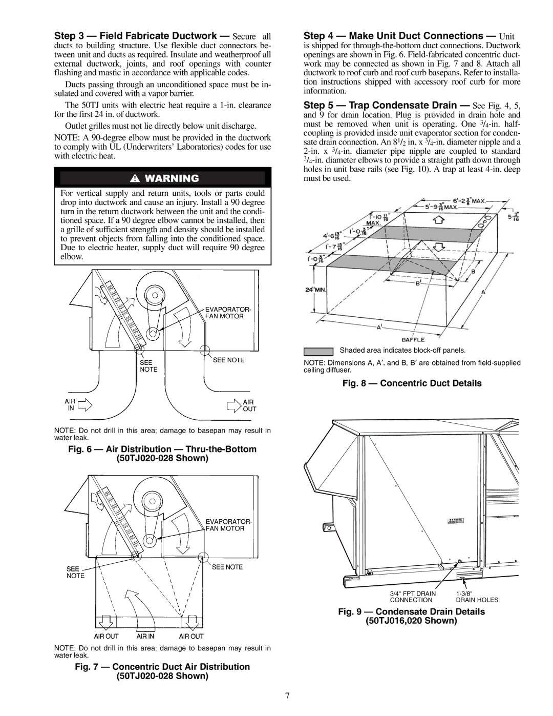
Shaded area indicates
NOTE: Dimensions A, A′, and B, B′ are obtained from
Fig. 8 — Concentric Duct Details
NOTE: Do not drill in this area; damage to basepan may result in water leak.
Fig. 6 — Air Distribution — Thru-the-Bottom
(50TJ020-028 Shown)
3/4" FPT DRAIN | |
CONNECTION | DRAIN HOLES |
Fig. 9 — Condensate Drain Details
(50TJ016,020 Shown)
NOTE: Do not drill in this area; damage to basepan may result in water leak.
Fig. 7 — Concentric Duct Air Distribution
(50TJ020-028 Shown)
7