VENTILATION AIR (Minimum Position Set Up) — If ven- tilation air is not required, skip this section. If ventilation air is required, perform the following:
1.The indoor fan must be on to set the ventilation air. Either put the thermostat in the continuous fan mode or jumper the R and G terminals at the rooftop unit con- nection board.
2.Locate the minimum position (MIN POS) potentiometer. Turn the potentiometer full CCW to fully close the out- door air dampers. Turn the potentiometer gradually clockwise (CW) to the desired position. See Fig. 16.
3.Replace the filter access panel. See Fig. 18. Ensure the fil- ter access panel is securely engaged.
4.Calculate the minimum airflow across the EconoMi$er.
a.Calculate % of outside air using the following formula.
% Outdoor air through EconoMi$er
Personal Injury Hazard. Avoid possible injury by keep- ing fingers away from damper blades.
Step 9 — Install All Accessories — After all the
MOTORMASTER® I CONTROL INSTALLATION (50TJ016 and 020 Only)
Install
% Outdoor air =
Mixture Temp – Return Air Temp
Outdoor Temp – Return Air Temp
b. Multiply total CFM by percentage outdoor air, this gives outdoor air volume in CFM.
To avoid damage to the refrigerant coils and electrical com- ponents, use recommended screw sizes only. Use care when drilling holes.
![]()
![]() Unoccupied Control (Part number on the control
Unoccupied Control (Part number on the control
must be
Outdoor Air Enthalpy |
|
|
|
CROUTENT001A00 |
| Unoccupied |
|
|
| Contact | 470 ohm |
|
|
| 5 watt |
| T | Violet | Resistor |
C |
| ||
O |
|
| |
O | U |
|
|
M | T T |
|
|
| PW |
|
|
|
| Tan |
OAT |
| Violet |
| ||
| ||
COM |
| W hite |
| ||
|
24 VAC must be present on BI for the system to be ![]()
![]() unoccupied.
unoccupied.
OAH |
| Red | ||||||||
| ||||||||||
+15V |
|
|
|
|
|
|
|
| Tan | |
|
|
|
|
|
|
|
| |||
RAT |
|
|
|
|
|
|
|
|
| |
| Violet | |||||||||
| ||||||||||
COM |
|
|
|
|
|
|
|
|
| |
RAH |
|
|
|
|
|
|
|
| W hite | |
+15V |
|
|
|
|
|
|
| Red | ||
|
|
|
|
|
|
| ||||
CO 2(+) |
|
|
|
|
| |||||
|
|
|
|
| ||||||
CO 2 |
|
|
|
|
| |||||
COM |
|
|
|
|
| |||||
DAT |
|
|
|
|
| |||||
|
|
|
|
| ||||||
|
|
|
|
| ||||||
COM |
|
|
|
|
| |||||
|
|
|
|
| ||||||
REM |
| |||||||||
POT |
|
| ||||||||
|
| |||||||||
COM |
|
| ||||||||
|
| |||||||||
LED |
|
| ||||||||
|
|
| ||||||||
|
|
| ||||||||
COM |
|
| ||||||||
|
| |||||||||
Violet
C TO
O U ![]()
![]()
M T T
PW
Remote
Minimum Position
1k ohm Potentiometer
20 mA LED
Remote
LED
Return Air Enthalpy
CRRETENT001A00
CO2 Sensors:
33ZCSENCO2
|
| 2 to 10 VDC at |
|
| 0 to 2000 ppm |
NOT 2 USED | VAC24 VA20 | Line |
|
| |
|
| Voltage |
1 |
|
|
- |
|
|
W iring Included
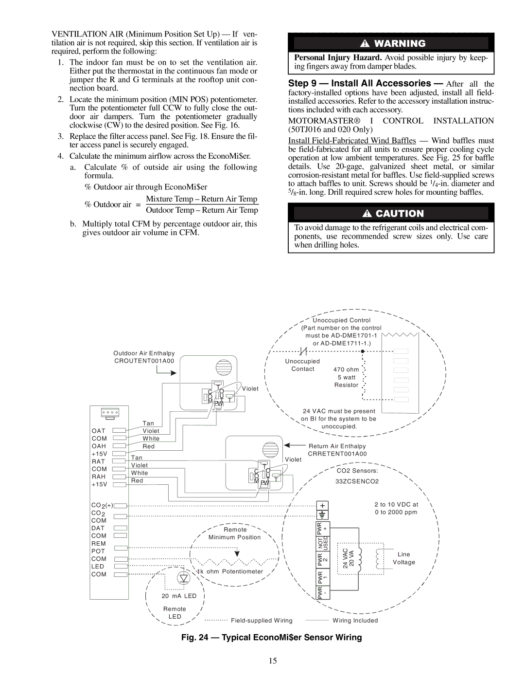
Fig. 24 — Typical EconoMi$er Sensor Wiring
15