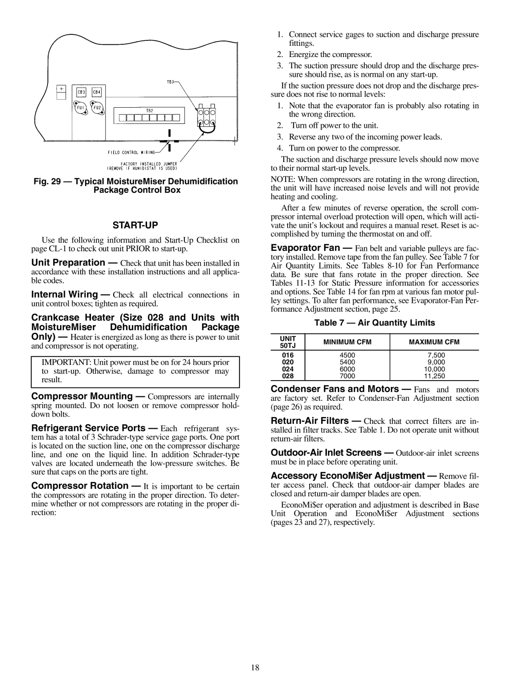
Fig. 29 — Typical MoistureMiser Dehumidification
Package Control Box
START-UP
Use the following information and
Unit Preparation — Check that unit has been installed in accordance with these installation instructions and all applica- ble codes.
Internal Wiring — Check all electrical connections in unit control boxes; tighten as required.
Crankcase Heater (Size 028 and Units with MoistureMiser Dehumidification Package Only) — Heater is energized as long as there is power to unit and compressor is not operating.
IMPORTANT: Unit power must be on for 24 hours prior to
Compressor Mounting — Compressors are internally spring mounted. Do not loosen or remove compressor hold- down bolts.
Refrigerant Service Ports — Each refrigerant sys- tem has a total of 3
Compressor Rotation — It is important to be certain the compressors are rotating in the proper direction. To deter- mine whether or not compressors are rotating in the proper di- rection:
1.Connect service gages to suction and discharge pressure fittings.
2.Energize the compressor.
3.The suction pressure should drop and the discharge pres- sure should rise, as is normal on any
If the suction pressure does not drop and the discharge pres- sure does not rise to normal levels:
1.Note that the evaporator fan is probably also rotating in the wrong direction.
2.Turn off power to the unit.
3.Reverse any two of the incoming power leads.
4.Turn on power to the compressor.
The suction and discharge pressure levels should now move to their normal
NOTE: When compressors are rotating in the wrong direction, the unit will have increased noise levels and will not provide heating and cooling.
After a few minutes of reverse operation, the scroll com- pressor internal overload protection will open, which will acti- vate the unit’s lockout and requires a manual reset. Reset is ac- complished by turning the thermostat on and off.
Evaporator Fan — Fan belt and variable pulleys are fac- tory installed. Remove tape from the fan pulley. See Table 7 for Air Quantity Limits. See Tables
Table 7 — Air Quantity Limits
UNIT | MINIMUM CFM | MAXIMUM CFM | |
50TJ | |||
|
| ||
016 | 4500 | 7,500 | |
020 | 5400 | 9,000 | |
024 | 6000 | 10,000 | |
028 | 7000 | 11,250 |
Condenser Fans and Motors — Fans and motors are factory set. Refer to
Accessory EconoMi$er Adjustment — Remove fil- ter access panel. Check that
EconoMi$er operation and adjustment is described in Base Unit Operation and EconoMi$er Adjustment sections (pages 23 and 27), respectively.
18