Step 5 — Select and Install Ductwork

The design and installation of the duct system must be in accordance with the standards of the NFPA for installation of non-residence type air conditioning and ventilating systems, NFPA 90A or residence-type, NFPA 90B and/or local codes and ordinances.

Select and size ductwork, supply-air registers, and return air grilles according to ASHRAE (American Society of Heating, Refrigeration, and Air Conditioning Engineers) recommendations. The unit has duct flanges on the supply- and return-air openings on the side of the unit.

!WARNING

PERSONAL INJURY HAZARD

Failure to follow this warning could result in personal injury or death.

For vertical supply and return units, tools or parts could drop into ductwork Install a 90 degree turn in the return ductwork between the unit and the conditioned space. If a 90 degree elbow cannot be installed, then a grille of sufficient strength and density should be installed to prevent objects from falling into the conditioned space. Units with electric heaters require 90 degree elbow in supply duct.

When designing and installing ductwork, consider the following:

1.All units should have field-supplied filters or accessory filter rack installed in the return-air side of the unit. Recommended sizes for filters are shown in Table 1.

2.Avoid abrupt duct size increases and reductions. Abrupt change in duct size adversely affects air performance.

CONFIGURING UNITS FOR DOWNFLOW (VERTICAL) DISCHARGE

!WARNING

ELECTRICAL SHOCK HAZARD

Failure to follow this warning could result in personal injury or death.

Before performing service or maintenance operations on the system, turn off main power to unit and install lockout tag. There may be more than one disconnect switch.

1.

Open all electrical disconnects and install lockout tag before


starting any service work.


2.

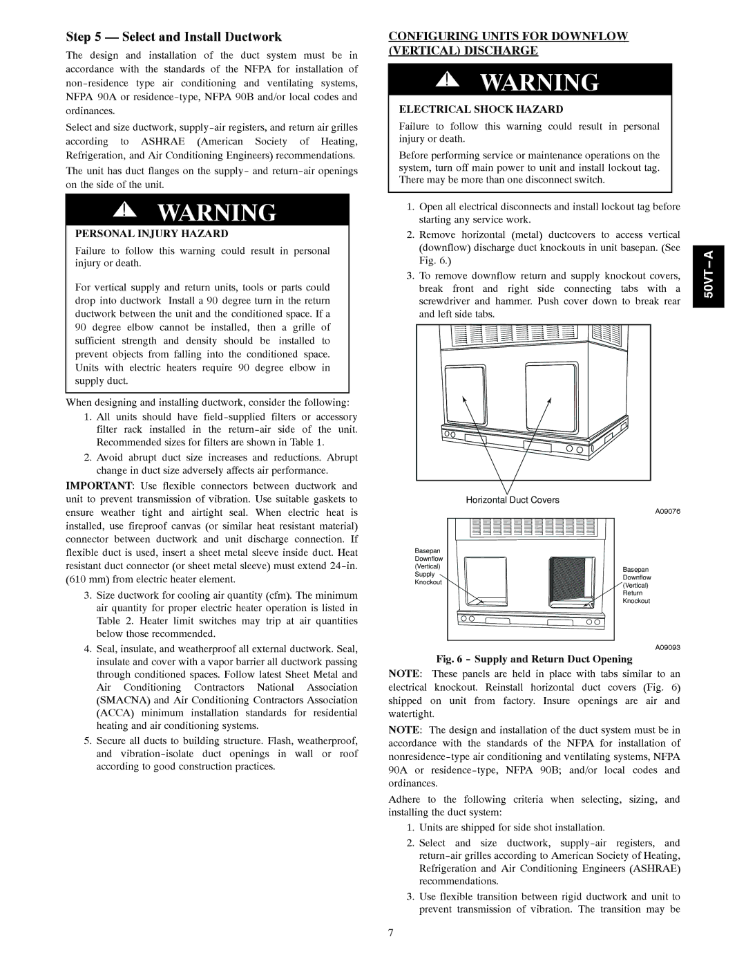
Remove horizontal (metal) ductcovers to access vertical


(downflow) discharge duct knockouts in unit basepan. (See


A


Fig. 6.)


--


3.

To remove downflow return and supply knockout covers,

50VT


break front and right side connecting tabs with a


screwdriver and hammer. Push cover down to break rear


and left side tabs.


IMPORTANT: Use flexible connectors between ductwork and unit to prevent transmission of vibration. Use suitable gaskets to ensure weather tight and airtight seal. When electric heat is installed, use fireproof canvas (or similar heat resistant material) connector between ductwork and unit discharge connection. If flexible duct is used, insert a sheet metal sleeve inside duct. Heat resistant duct connector (or sheet metal sleeve) must extend 24-in. (610 mm) from electric heater element.

3. Size ductwork for cooling air quantity (cfm). The minimum

air quantity for proper electric heater operation is listed in

Table 2. Heater limit switches may trip at air quantities

below those recommended.

Horizontal Duct Covers

Basepan Downflow (Vertical) Supply Knockout

A09076

Basepan Downflow (Vertical) Return Knockout

4. Seal, insulate, and weatherproof all external ductwork. Seal,

insulate and cover with a vapor barrier all ductwork passing

through conditioned spaces. Follow latest Sheet Metal and

Air Conditioning Contractors National Association

(SMACNA) and Air Conditioning Contractors Association

(ACCA) minimum installation standards for residential

heating and air conditioning systems.

5. Secure all ducts to building structure. Flash, weatherproof,

and vibration-isolate duct openings in wall or roof

according to good construction practices.

A09093

Fig. 6 - Supply and Return Duct Opening

NOTE: These panels are held in place with tabs similar to an electrical knockout. Reinstall horizontal duct covers (Fig. 6) shipped on unit from factory. Insure openings are air and watertight.

NOTE: The design and installation of the duct system must be in accordance with the standards of the NFPA for installation of nonresidence-type air conditioning and ventilating systems, NFPA 90A or residence-type, NFPA 90B; and/or local codes and ordinances.

Adhere to the following criteria when selecting, sizing, and installing the duct system:

1.Units are shipped for side shot installation.

2.Select and size ductwork, supply-air registers, and return-air grilles according to American Society of Heating, Refrigeration and Air Conditioning Engineers (ASHRAE) recommendations.

3.Use flexible transition between rigid ductwork and unit to prevent transmission of vibration. The transition may be

7

Page 7
Image 7
Carrier 50VT-A installation instructions Select and Install Ductwork, Personal Injury Hazard

50VT-A specifications

Carrier’s 50VT-A and 50EZ-A series exemplify cutting-edge advancements in heating, ventilation, and air conditioning (HVAC) technology. These products are engineered to meet diverse climate control needs in residential and commercial applications while ensuring operational efficiency and superior indoor air quality.

The Carrier 50VT-A series stands out with its variable-speed technology, which allows for precise temperature control by adjusting the cooling or heating output based on current demand. This capability not only optimizes energy consumption but also enhances comfort by eliminating temperature swings. The 50VT-A units are equipped with hybrid heat technology, which enables seamless integration with alternative heating sources, providing flexibility in energy use.

On the other hand, the Carrier 50EZ-A offers a unique solution for those seeking efficient and reliable climate control in a more compact design. This series incorporates advanced inverter technology, which continuously adjusts the compressor speed, ensuring that the system operates at the utmost efficiency regardless of environmental conditions. The result is significant energy savings and quieter operation compared to traditional units.

Both series feature intelligent refrigerant management, utilizing R-410A refrigerant, which is environmentally friendly and designed to reduce greenhouse gas emissions. The systems are engineered with robust insulation and sound-dampening materials, minimizing noise levels for a peaceful indoor environment.

In addition to their impressive technical specifications, the Carrier 50VT-A and 50EZ-A units come equipped with smart controls, allowing users to monitor and adjust settings remotely through mobile applications. This connectivity feature empowers homeowners and businesses to manage energy consumption, set schedules, and receive maintenance alerts, ensuring optimal performance at all times.

Durability is an important characteristic of both series, as they are designed to withstand various environmental conditions. With corrosion-resistant coatings and high-grade materials, these units promise longevity and reliable performance over their operational lifespan.

In summary, Carrier’s 50VT-A and 50EZ-A series offer an innovative blend of efficiency, advanced technology, and user-friendly features. Whether for residential or commercial applications, these systems provide exceptional comfort, lower energy costs, and an environmentally conscious choice for modern HVAC solutions.