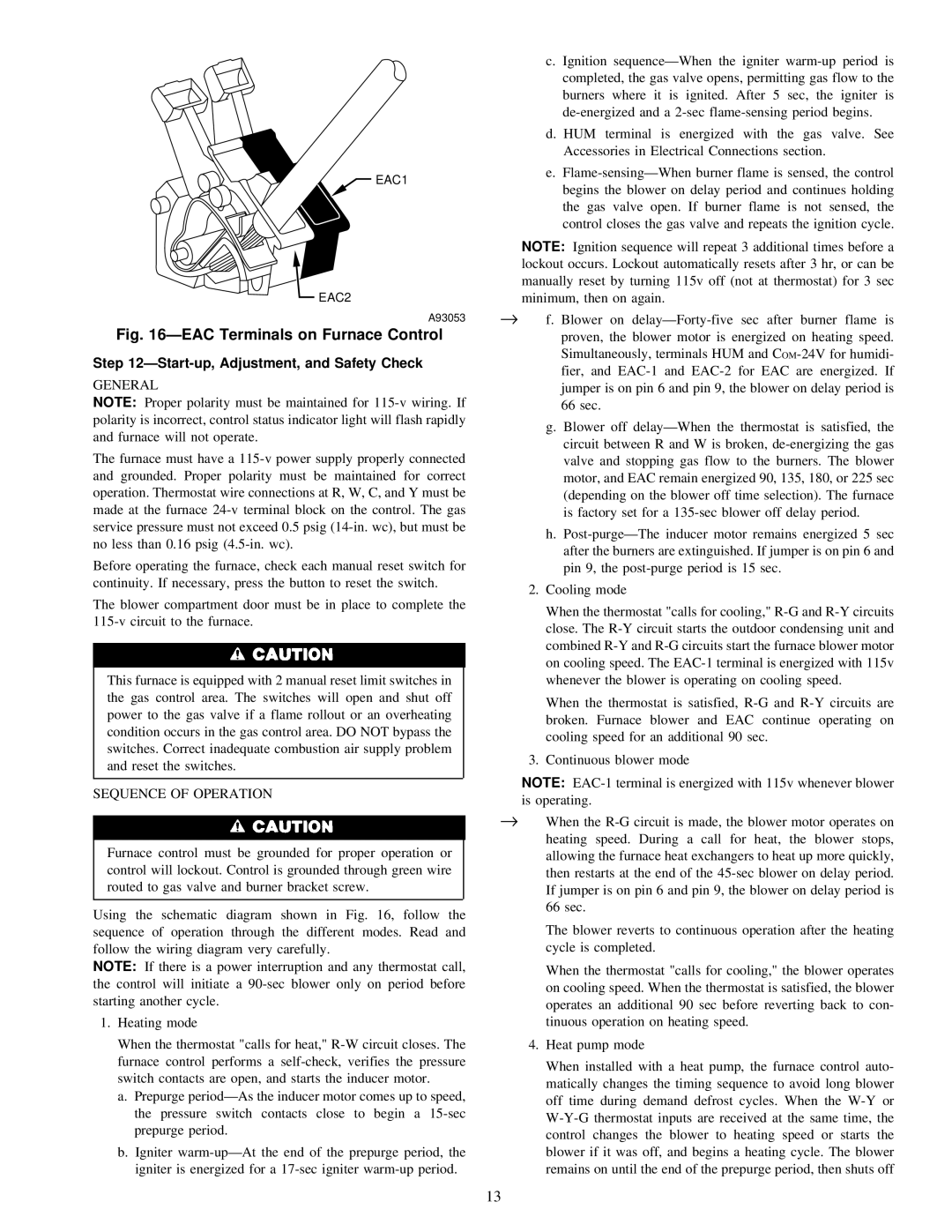
EAC1
EAC1
EAC2
A93053
Fig. 16ÐEAC Terminals on Furnace Control
Step 12ÐStart-up, Adjustment, and Safety Check
GENERAL
NOTE: Proper polarity must be maintained for 115-v wiring. If polarity is incorrect, control status indicator light will flash rapidly and furnace will not operate.
The furnace must have a 115-v power supply properly connected and grounded. Proper polarity must be maintained for correct operation. Thermostat wire connections at R, W, C, and Y must be made at the furnace 24-v terminal block on the control. The gas service pressure must not exceed 0.5 psig (14-in. wc), but must be no less than 0.16 psig (4.5-in. wc).
Before operating the furnace, check each manual reset switch for continuity. If necessary, press the button to reset the switch.
The blower compartment door must be in place to complete the 115-v circuit to the furnace.
This furnace is equipped with 2 manual reset limit switches in the gas control area. The switches will open and shut off power to the gas valve if a flame rollout or an overheating condition occurs in the gas control area. DO NOT bypass the switches. Correct inadequate combustion air supply problem and reset the switches.
SEQUENCE OF OPERATION
Furnace control must be grounded for proper operation or control will lockout. Control is grounded through green wire routed to gas valve and burner bracket screw.
Using the schematic diagram shown in Fig. 16, follow the sequence of operation through the different modes. Read and follow the wiring diagram very carefully.
NOTE: If there is a power interruption and any thermostat call, the control will initiate a 90-sec blower only on period before starting another cycle.
1.Heating mode
When the thermostat "calls for heat," R-W circuit closes. The furnace control performs a self-check, verifies the pressure switch contacts are open, and starts the inducer motor.
a.Prepurge periodÐAs the inducer motor comes up to speed, the pressure switch contacts close to begin a 15-sec prepurge period.
b.Igniter warm-upÐAt the end of the prepurge period, the igniter is energized for a 17-sec igniter warm-up period.
c. Ignition sequenceÐWhen the igniter warm-up period is completed, the gas valve opens, permitting gas flow to the burners where it is ignited. After 5 sec, the igniter is de-energized and a 2-sec flame-sensing period begins.
d. HUM terminal is energized with the gas valve. See Accessories in Electrical Connections section.
e.Flame-sensingÐWhen burner flame is sensed, the control begins the blower on delay period and continues holding the gas valve open. If burner flame is not sensed, the control closes the gas valve and repeats the ignition cycle.
NOTE: Ignition sequence will repeat 3 additional times before a lockout occurs. Lockout automatically resets after 3 hr, or can be manually reset by turning 115v off (not at thermostat) for 3 sec minimum, then on again.
→f. Blower on delayÐForty-five sec after burner flame is proven, the blower motor is energized on heating speed. Simultaneously, terminals HUM and COM-24V for humidi- fier, and EAC-1 and EAC-2 for EAC are energized. If jumper is on pin 6 and pin 9, the blower on delay period is 66 sec.
g.Blower off delayÐWhen the thermostat is satisfied, the circuit between R and W is broken, de-energizing the gas valve and stopping gas flow to the burners. The blower motor, and EAC remain energized 90, 135, 180, or 225 sec (depending on the blower off time selection). The furnace is factory set for a 135-sec blower off delay period.
h.Post-purgeÐThe inducer motor remains energized 5 sec after the burners are extinguished. If jumper is on pin 6 and pin 9, the post-purge period is 15 sec.
2.Cooling mode
When the thermostat "calls for cooling," R-G and R-Y circuits close. The R-Y circuit starts the outdoor condensing unit and combined R-Y and R-G circuits start the furnace blower motor on cooling speed. The EAC-1 terminal is energized with 115v whenever the blower is operating on cooling speed.
When the thermostat is satisfied, R-G and R-Y circuits are broken. Furnace blower and EAC continue operating on cooling speed for an additional 90 sec.
3.Continuous blower mode
NOTE: EAC-1 terminal is energized with 115v whenever blower is operating.
→When the R-G circuit is made, the blower motor operates on heating speed. During a call for heat, the blower stops, allowing the furnace heat exchangers to heat up more quickly, then restarts at the end of the 45-sec blower on delay period. If jumper is on pin 6 and pin 9, the blower on delay period is 66 sec.
The blower reverts to continuous operation after the heating cycle is completed.
When the thermostat "calls for cooling," the blower operates on cooling speed. When the thermostat is satisfied, the blower operates an additional 90 sec before reverting back to con- tinuous operation on heating speed.
4.Heat pump mode
When installed with a heat pump, the furnace control auto- matically changes the timing sequence to avoid long blower off time during demand defrost cycles. When the W-Y or W-Y-G thermostat inputs are received at the same time, the control changes the blower to heating speed or starts the blower if it was off, and begins a heating cycle. The blower remains on until the end of the prepurge period, then shuts off