Press ADVANCE TIME/DAY button until desired start time is displayed.
6.Adjust setpoints.
Adjust setpoints using up and down buttons until desired temperatures for the selected time period appear in display. These setpoints will be used during the time period currently displayed in clock window.
7.Complete time period programming.
Repeat 4 through 6 to program remaining weekly period start times. Each weekly period can be programmed with 4 differ- ent time periods.
8.Complete weekly schedule.
After completing start time programming, press SELECT MIN/HR/DAY until MTWTHF reappears in clock display. Repeat steps 3 through 7 to program weekly periods. Once finished, this will complete programming of 1 zone.
9.Program a different zone.
To program a different zone, turn rotary switch to desired zone to be programmed and repeat 2 through 8.
10.Exit program mode.
Exit program mode by pressing SET TIME/TEMP SCHED- ULES button.
Overriding Programming
To override time programming, press any setpoint button. This will also adjust setpoints for override period. Once setpoints are adjusted, they will not change until the next programmed time period for that zone.
If HOLD TEMPERATURES button is pressed, then current setpoints will not change with time, but remain at last values entered for as long as hold mode is active.
To release hold mode, press HOLD TEMPERATURE button a second time.
The controller display will show the word HOLD whenever hold mode is active.
Temperature Sensor Calibration
NOTE: Temperature sensors are factory calibrated; however, field calibration is recommended.
The setpoint display shows actual temperature (Fahrenheit or Celsius).
The upper left-hand corner of display indicates the whole number value. The lower right-hand corner indicated the tenths.
Pressing either HEAT or COOL button raises or lowers displayed temperature by 1/10 of a degree.
If temperature readings are not stable within 0.5°F, refer to troubleshooting section for details.
Damper Service Mode
The Damper Service Mode can be selected to check full operation of each zone damper independently. The controller display shows zone number in the upper left digits, and damper position in the lower right digits. The left hand setpoint buttons will toggle the zone number (1-4) and 5.
NOTE: No. 5 not used for damper service mode, see below for details when setting motorized bypass damper pressure relief limit.
When this mode is selected, all 4 zone dampers are activated and opened to position 15. (See Table 2.) Fan will energize. Use right hand setpoint buttons to toggle down from position 15 to position
0.This feature can verify that each zone damper is operating properly by manually opening and closing each zone. When rotary switch dial is moved onto another position, Damper Service Mode will be cleared and controller will resume normal operation.
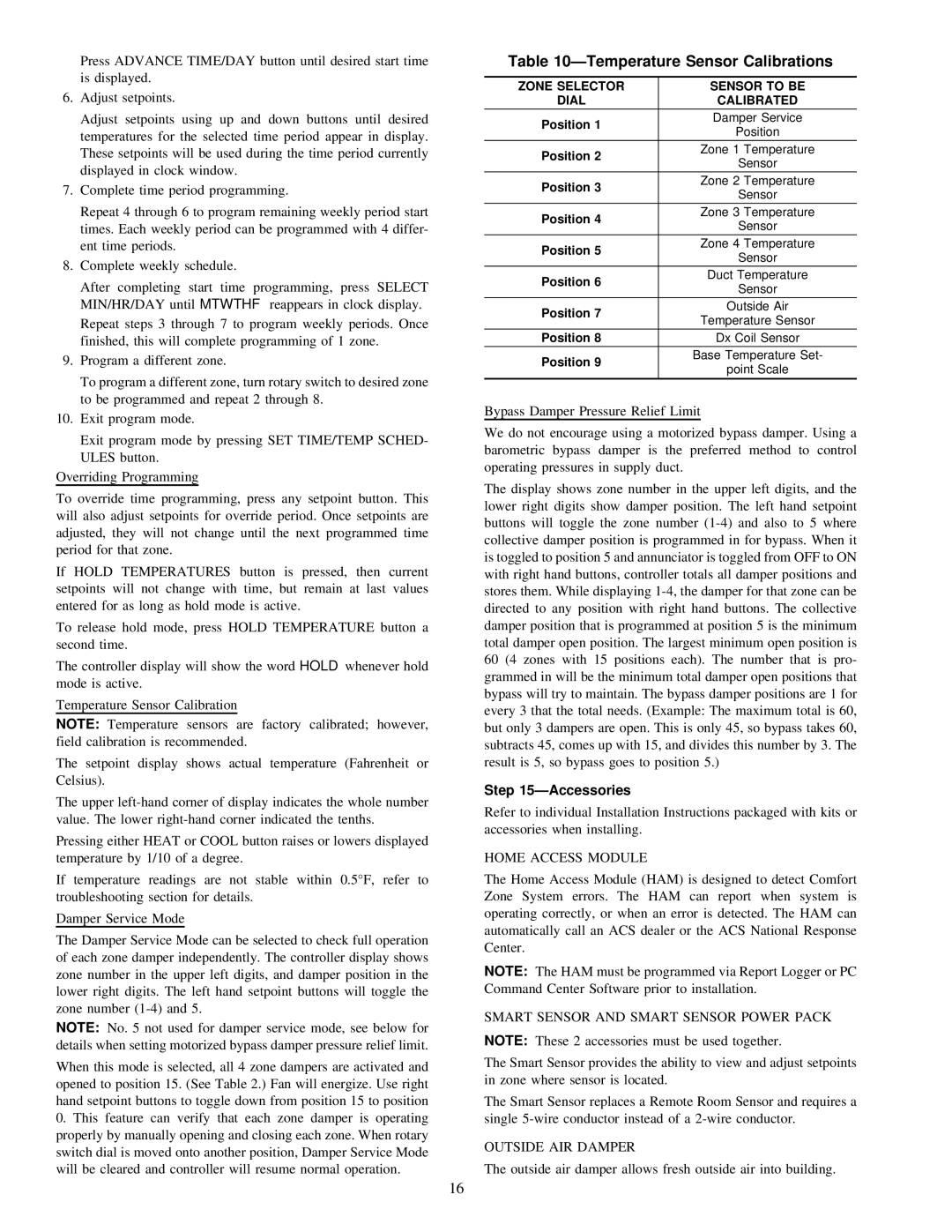
Table 10ÐTemperature Sensor Calibrations
| ZONE SELECTOR | SENSOR TO BE |
| DIAL | CALIBRATED |
| Position 1 | Damper Service |
| Position |
| |
| Position 2 | Zone 1 Temperature |
| Sensor |
| |
| Position 3 | Zone 2 Temperature |
| Sensor |
| |
| Position 4 | Zone 3 Temperature |
| Sensor |
| |
| Position 5 | Zone 4 Temperature |
| Sensor |
| |
| Position 6 | Duct Temperature |
| Sensor |
| |
| Position 7 | Outside Air |
| Temperature Sensor |
| |
| Position 8 | Dx Coil Sensor |
| Position 9 | Base Temperature Set- |
| point Scale |
| |
| | |
Bypass Damper Pressure Relief Limit
We do not encourage using a motorized bypass damper. Using a barometric bypass damper is the preferred method to control operating pressures in supply duct.
The display shows zone number in the upper left digits, and the lower right digits show damper position. The left hand setpoint buttons will toggle the zone number (1-4) and also to 5 where collective damper position is programmed in for bypass. When it is toggled to position 5 and annunciator is toggled from OFF to ON with right hand buttons, controller totals all damper positions and stores them. While displaying 1-4, the damper for that zone can be directed to any position with right hand buttons. The collective damper position that is programmed at position 5 is the minimum total damper open position. The largest minimum open position is 60 (4 zones with 15 positions each). The number that is pro- grammed in will be the minimum total damper open positions that bypass will try to maintain. The bypass damper positions are 1 for every 3 that the total needs. (Example: The maximum total is 60, but only 3 dampers are open. This is only 45, so bypass takes 60, subtracts 45, comes up with 15, and divides this number by 3. The result is 5, so bypass goes to position 5.)
Step 15ÐAccessories
Refer to individual Installation Instructions packaged with kits or accessories when installing.
HOME ACCESS MODULE
The Home Access Module (HAM) is designed to detect Comfort Zone System errors. The HAM can report when system is operating correctly, or when an error is detected. The HAM can automatically call an ACS dealer or the ACS National Response Center.
NOTE: The HAM must be programmed via Report Logger or PC Command Center Software prior to installation.
SMART SENSOR AND SMART SENSOR POWER PACK
NOTE: These 2 accessories must be used together.
The Smart Sensor provides the ability to view and adjust setpoints in zone where sensor is located.
The Smart Sensor replaces a Remote Room Sensor and requires a single 5-wire conductor instead of a 2-wire conductor.
OUTSIDE AIR DAMPER
The outside air damper allows fresh outside air into building.