Manuals
/
Casio
/
Communications
/
PDAs & Smartphones
Casio
IT-2000
installation manual
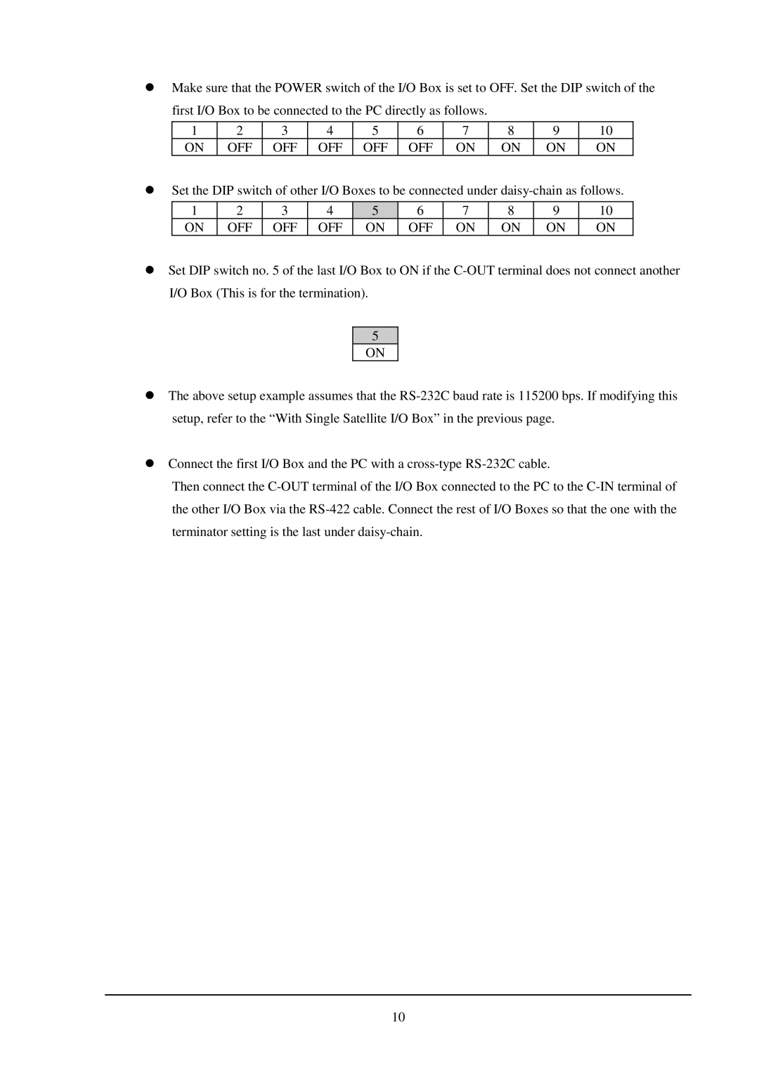
I/O Box This is for the termination
Models:
IT-2000
1
10
31
31
Download
31 pages
30.53 Kb
7
8
9
10
11
12
13
14
Page 10
Image 10
Page 9
Page 11
Page 10
Image 10
Page 9
Page 11
Contents
IT-2000 I/O Box Installation Manual
April
Copyright 1998. All rights reserved
Version
Table of Contents
Appendix
1. Overview
2.1 Options and Software
2. System Configuration and Installation Method
Software
2.2.1 With Single I/O Box
2.2 System Configuration
2.2.2 With Multiple I/O Boxes
2.2.3 With Single Master I/O Box
2.2.4 With Multiple Master I/O Boxes
2.2.5 With Master and Satellite I/O Boxes
2.3 Installation Method
With single Satellite I/O Box
2.3.1 Setup of Satellite I/O Box
With Multiple Satellite I/O Boxes
I/O Box This is for the termination
2.3.2 Setup of Master I/O Box
2.3.3 Setup of Satellite I/O Box to Master I/O Box
Connection
2.3.4 Setup of PC
Startup
Environment Setup
3.1.1 Specifying Files from PC
3. Operation Method
3.1 File Upload
Operation on PC
FLINK.DLL of Windows 3.1 version
Operation on IT-2000
DoFLINK argc, argv argc = argv = fl
3.1.2 Specifying Files from IT-2000
FLINK.EXE of MS-DOS version
FLINK.DLL of Windows 3.1 version
3.2 File Download
3.2.1 Specifying Files from PC
FLINK.EXE of MS-DOS version
3.2.2 Specifying Files from IT-2000
FLINK /R CFILE D
DoFLINK argc, argv argc = argv = fl , /r, CFILE, Dyyy
4. Error Codes and Error Messages
Categ
Detai
Table 4.2 Error codes and error messages
Common to Satellite and Master I/O Boxes
5. Q and A
Satellite I/O Box
Master I/O Box
Can I update the version of Master I/O Box firmware ?
IT-2000 Upload/Download Utility Manual
6. Reference Manuals
IT-2000 Technical Reference Manual IT-2000 Hardware Manual
SCSI Board
7. List of SCSI Boards and SCSI Cables
SCSI Cable
Syntax of the Installer Command
Appendix Installation Method of Upload/Download Utility
Installation
setup
Top
Page
Image
Contents