OPERATION | ||
|
|
|
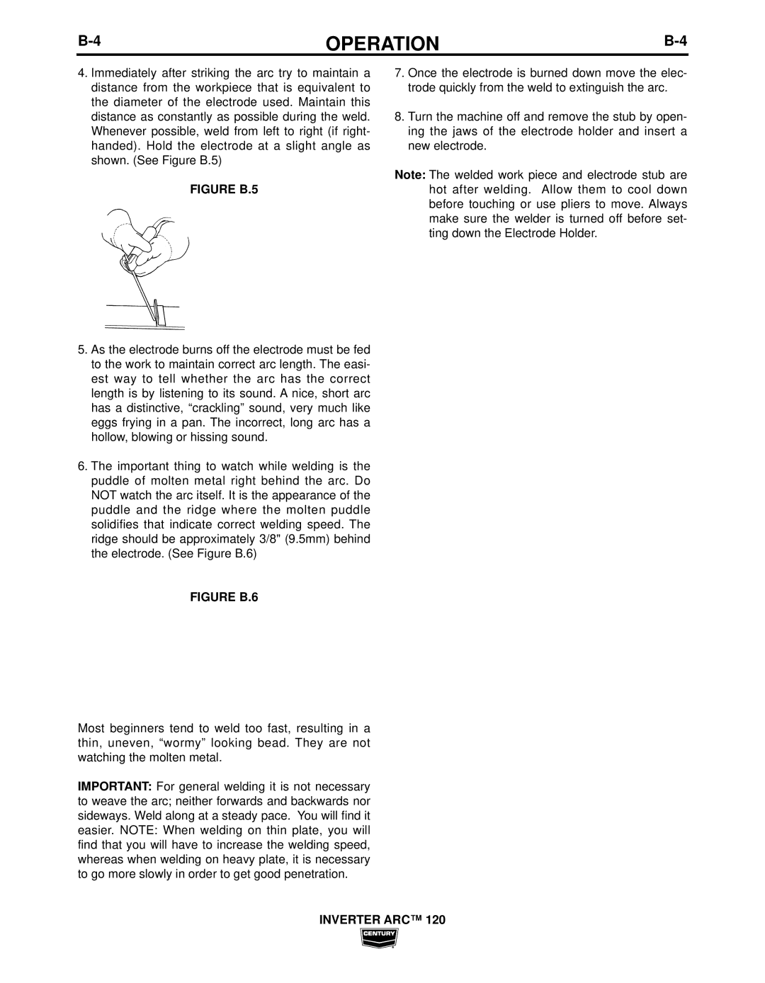
4.Immediately after striking the arc try to maintain a distance from the workpiece that is equivalent to the diameter of the electrode used. Maintain this distance as constantly as possible during the weld. Whenever possible, weld from left to right (if right- handed). Hold the electrode at a slight angle as shown. (See Figure B.5)
FIGURE B.5
5.As the electrode burns off the electrode must be fed to the work to maintain correct arc length. The easi- est way to tell whether the arc has the correct length is by listening to its sound. A nice, short arc has a distinctive, “crackling” sound, very much like eggs frying in a pan. The incorrect, long arc has a hollow, blowing or hissing sound.
6.The important thing to watch while welding is the puddle of molten metal right behind the arc. Do NOT watch the arc itself. It is the appearance of the puddle and the ridge where the molten puddle solidifies that indicate correct welding speed. The ridge should be approximately 3/8" (9.5mm) behind the electrode. (See Figure B.6)
FIGURE B.6
Most beginners tend to weld too fast, resulting in a thin, uneven, “wormy” looking bead. They are not watching the molten metal.
IMPORTANT: For general welding it is not necessary to weave the arc; neither forwards and backwards nor sideways. Weld along at a steady pace. You will find it easier. NOTE: When welding on thin plate, you will find that you will have to increase the welding speed, whereas when welding on heavy plate, it is necessary to go more slowly in order to get good penetration.
7.Once the electrode is burned down move the elec- trode quickly from the weld to extinguish the arc.
8.Turn the machine off and remove the stub by open- ing the jaws of the electrode holder and insert a new electrode.
Note: The welded work piece and electrode stub are hot after welding. Allow them to cool down before touching or use pliers to move. Always make sure the welder is turned off before set- ting down the Electrode Holder.