Chateau™
Operating Instructions
Glass Information
Only glass approved by CFM Corporation should be used on this fireplace.
•The use of any
•Care must be taken to avoid breakage of the glass.
•Do not operate appliance with glass front removed, cracked or broken.
•A replacement glass frame assembly (complete with gasket) is available through your CFM Corporation dealer and should only be installed by a licensed qualified service person.
��������
��������������
������������
������������������
�������������
��������������������
���������������
Glass Frame Assembly Removal
1.Turn the fireplace OFF (including the pilot).
2.If the unit has been operating allow time for the components to cool.
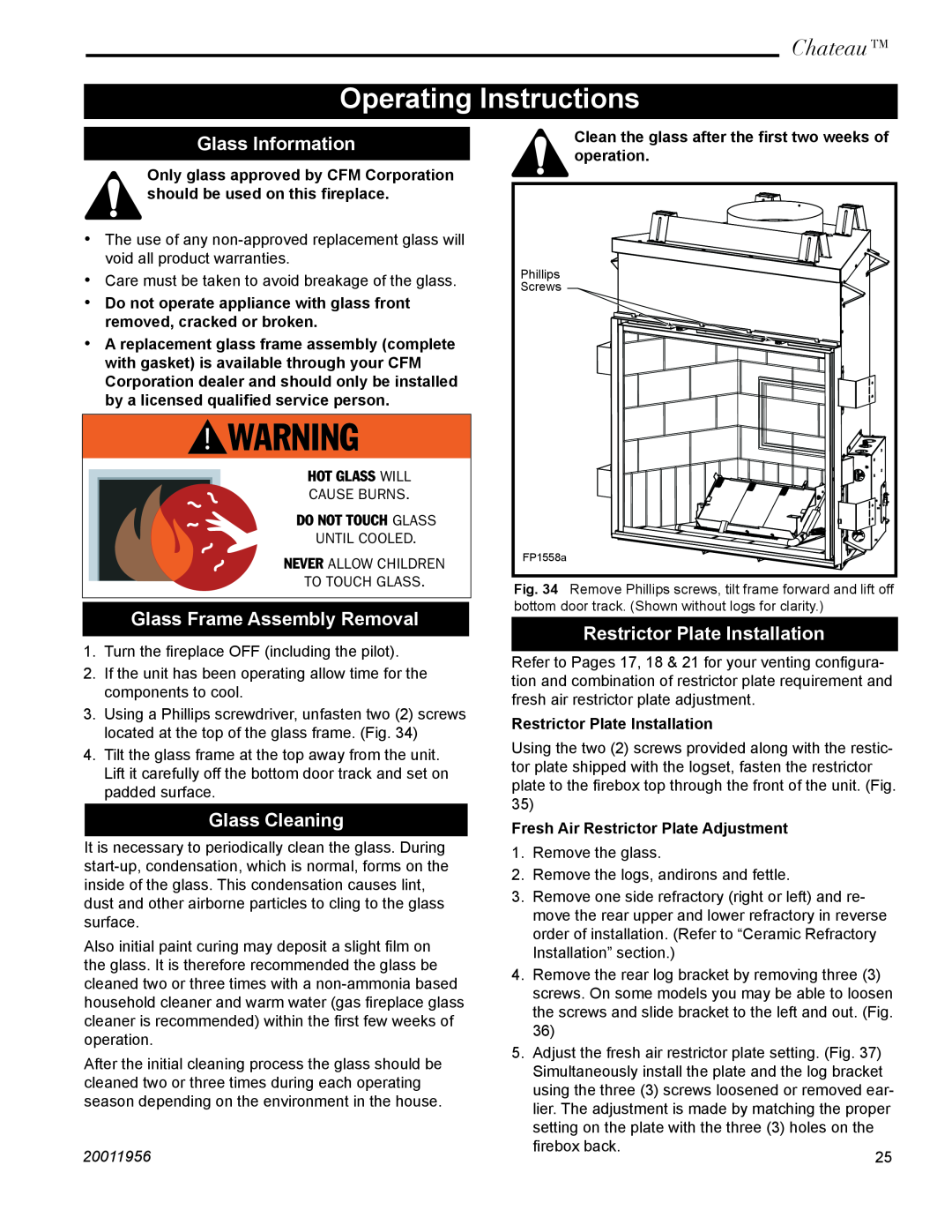
3.Using a Phillips screwdriver, unfasten two (2) screws located at the top of the glass frame. (Fig. 34)
4.Tilt the glass frame at the top away from the unit. Lift it carefully off the bottom door track and set on padded surface.
Glass Cleaning
It is necessary to periodically clean the glass. During
Also initial paint curing may deposit a slight film on the glass. It is therefore recommended the glass be cleaned two or three times with a
After the initial cleaning process the glass should be cleaned two or three times during each operating season depending on the environment in the house.
20011956
Clean the glass after the first two weeks of operation.
Phillips
Screws
FP1558a
Fig. 34 Remove Phillips screws, tilt frame forward and lift off bottom door track. (Shown without logs for clarity.)
Restrictor Plate Installation
Refer to Pages 17, 18 & 21 for your venting configura- tion and combination of restrictor plate requirement and fresh air restrictor plate adjustment.
Restrictor Plate Installation
Using the two (2) screws provided along with the restic- tor plate shipped with the logset, fasten the restrictor plate to the firebox top through the front of the unit. (Fig. 35)
Fresh Air Restrictor Plate Adjustment
1. Remove the glass.
2. Remove the logs, andirons and fettle.
3. Remove one side refractory (right or left) and re- move the rear upper and lower refractory in reverse order of installation. (Refer to “Ceramic Refractory Installation” section.)
4. Remove the rear log bracket by removing three (3) screws. On some models you may be able to loosen the screws and slide bracket to the left and out. (Fig. 36)
5. Adjust the fresh air restrictor plate setting. (Fig. 37) Simultaneously install the plate and the log bracket using the three (3) screws loosened or removed ear- lier. The adjustment is made by matching the proper setting on the plate with the three (3) holes on the
firebox back.
25