Gas Specifications
|
|
| Max. | Min. |
|
| Gas | Input | Input |
Model | Fuel | Control | BTU/hr | BTU/hr |
DVT38IN | Natural Gas | American Flame | 46,000 | 32,000 |
DVT38IP | Propane | 46,000 | 36,000 | |
DVT44IN | Natural Gas | with | 60,000 | 37,000 |
DVT44IP | Propane | 7.5V DC Hi/Lo | 60,000 | 45,000 |
Gas Inlet and Manifold Pressures
| Natural | LP (Propane) |
Minimum Inlet Pressure | 5.5” w.c. | 11.0” w.c. |
Maximum Inlet Pressure | 14.0” w.c. | 14.0” w.c. |
Manifold Pressure | 3.5” w.c. | 10.0” w.c. |
|
|
|
High Elevations
Input ratings are shown in BTU per hour and are certified without deration for elevations up to 4,500 feet (1,370 m) above sea level.
For elevations above 4,500 feet (1,370 m) in USA, installations must be in accordance with the current ANSI Z223.1/NFPA 54 and/or local codes having jurisdiction.
In Canada, please consult provincial and/or local authorities having jurisdiction for installations at elevations above 4,500 feet (1,370 m).
WARNING: Improper installation, adjust- ment, alteration, service or maintenance can cause injury or property damage. Refer to this manual for correct installation and operational procedures. For assistance or additional information consult a qualified installer, service agency, or the gas supplier.
Chateau™
Gas Line Installation
When purging gas line the front glass must be removed.
A gas shut off valve must be installed on the gas pipe line going into the appliance within easy access. Refer to local codes.
The gas pipeline can be brought in through the top of the valve box assembly.
The gas line connection can be made with properly tinned 1/2” copper tubing or 1/2” gas tight. Some municipalities have additional local codes, it is always best to consult your local authority and the
For USA installations consult the current National Fuel Gas Code, ANSI Z223.1/NFPA 54.
|
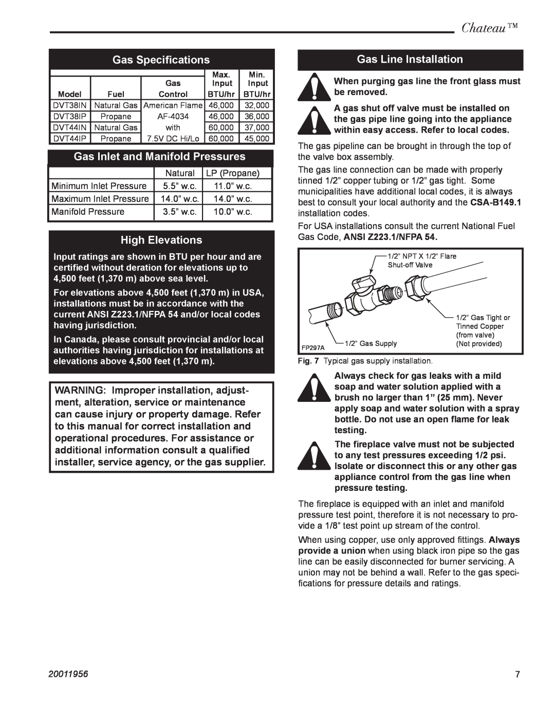
| 1/2” NPT X 1/2” Flare | |
|
|
| |
|
|
| 1/2” Gas Tight or |
|
|
| Tinned Copper |
|
|
| (from valve) |
FP297A | 1/2” Gas Supply | (Not provided) | |
|
| ||
Fig. 7 | Typical gas supply installation. |
| |
Always check for gas leaks with a mild soap and water solution applied with a brush no larger than 1” (25 mm). Never apply soap and water solution with a spray bottle. Do not use an open flame for leak testing.
The fireplace valve must not be subjected to any test pressures exceeding 1/2 psi. Isolate or disconnect this or any other gas appliance control from the gas line when pressure testing.
The fireplace is equipped with an inlet and manifold pressure test point, therefore it is not necessary to pro- vide a 1/8” test point up stream of the control.
When using copper, use only approved fittings. Always provide a union when using black iron pipe so the gas line can be easily disconnected for burner servicing. A union may not be behind a wall. Refer to the gas speci- fications for pressure details and ratings.
20011956 | 7 |