Cable Connectors
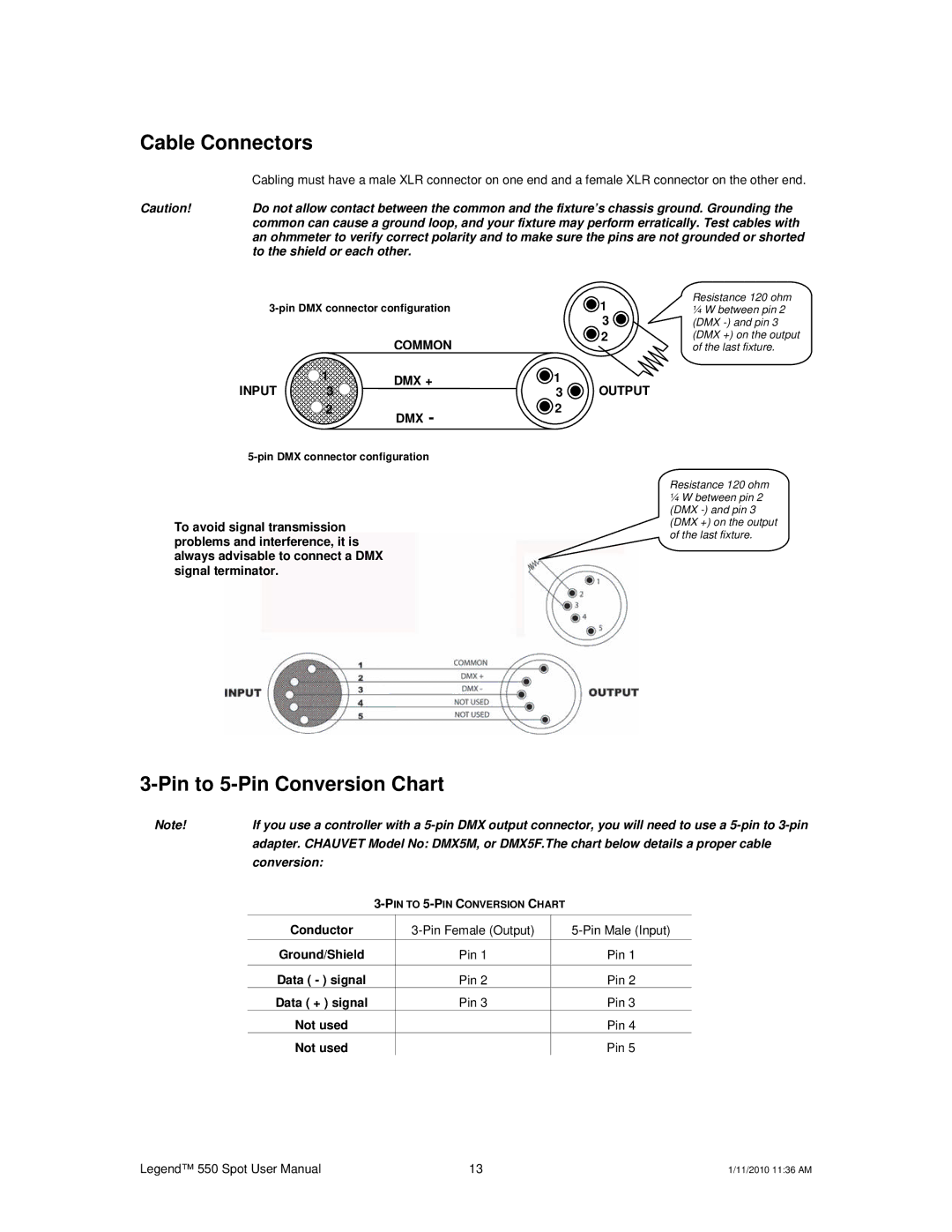
| Cabling must have a male XLR connector on one end and a female XLR connector on the other end. |
Caution! | Do not allow contact between the common and the fixture’s chassis ground. Grounding the |
| common can cause a ground loop, and your fixture may perform erratically. Test cables with |
| an ohmmeter to verify correct polarity and to make sure the pins are not grounded or shorted |
| to the shield or each other. |
| 1 | |||
|
|
|
| 3 |
|
| COMMON |
| 2 |
|
|
|
| |
INPUT | 1 | DMX + | 1 | OUTPUT |
3 |
| 3 | ||
| 2 | DMX - | 2 |
|
|
|
|
| |
Resistance 120 ohm
¼W between pin 2 (DMX
To avoid signal transmission problems and interference, it is always advisable to connect a DMX signal terminator.
Resistance 120 ohm
¼W between pin 2 (DMX
3-Pin to 5-Pin Conversion Chart
Note! | If you use a controller with a |
| adapter. CHAUVET Model No: DMX5M, or DMX5F.The chart below details a proper cable |
| conversion: |
Conductor | ||
Ground/Shield | Pin 1 | Pin 1 |
Data ( - ) signal | Pin 2 | Pin 2 |
Data ( + ) signal | Pin 3 | Pin 3 |
Not used |
| Pin 4 |
Not used |
| Pin 5 |
Legend™ 550 Spot User Manual | 13 | 1/11/2010 11:36 AM |